Do you have a question about the ICStation CAI-201 and is the answer not in the manual?
Guide to navigate settings, change values, and exit. Auto-quits after 15s inactivity.
Simultaneous press of SET and UP for 3s resets the clock to 8:00 with sound.
Press UP to change year while it twinkles. SET to confirm and move to next setting.
Set month and day sequentially using UP and SET buttons. Week is auto-set.
Set hour and minute by pressing SET to toggle between them and UP to adjust.
Switch between 24-hour and 12-hour format by pressing UP after releasing SET.
Defines the start (7 AM) and end (9 PM) for hourly alarms. Setting 7-7 disables it.
Enable/disable first alarm (ON:A1 / --:A1). Set alarm time (HH:MM) if enabled.
Enable/disable second alarm (ON:A2 / --:A2). Set alarm time (HH:MM) if enabled.
Enable/disable third alarm (ON:A3 / --:A3). Set alarm time (HH:MM) if enabled.
Configure alarm for weekdays only (ON:E) or all week (Mon-Sun).
Enable auto brightness (ON:L) for reduced night brightness or disable (L) for constant brightness.
Adjust brightness to L-1 (low), L-2 (medium), or L-3 (high). Not applicable if auto-brightness is on.
Displays current temperature. Press UP to fine-tune temperature by +/- 1 degree.
Toggle temperature display between Celsius (°C) and Fahrenheit (°F).
Select color modes: dC-1 (random), dC-2 (optional per item), dC-3 (individual tube color).
Choose alarm music from three options: 'For Elise', 'Ode to Joy', or 'Spanish Bullfighter'.
Set automatic daily time adjustment (seconds) for correction (de-0 for no correction).
Configure display cycle: dP-1 (Time), dP-2 (Temp), dP-3 (Date), dP-4 (Time-Temp-Date-Week).
| Type | Digital Clock |
|---|---|
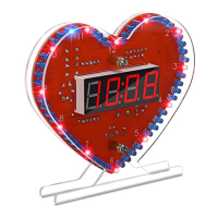
| Display | LED |
| Display Color | Red |
| Power Supply | DC 5V |
| Time Format | 12/24 Hour |