Do you have a question about the Ideal Air 700875 and is the answer not in the manual?
Details performance data, power supply, dimensions, and operating ranges for all models.
Explains the construction of the rotary type compressor, detailing its drive and compression mechanisms.
Describes the four stages of compressor operation: start, suction, discharge, and completion of compression.
Presents the electrical schematic for the 700870 model, showing component connections and wiring.
Presents the electrical schematic for the 700875 and 700877 models, showing component connections and wiring.
Details the functions of each button on the control panel, including Power, Blower, Spot/Cool, and Room/Cool.
Explains the 120-second time delay program for compressor protection against heavy loads.
Lists alarm displays, problems, causes, and corrective actions for system self-diagnostics.
Covers safe transport, unit placement, grounding, and operating temperature ranges.
Warns against wet/explosive environments, wet hands, foreign objects, chemicals, and using control panel.
Addresses extension cord use, damaged cords, filter maintenance, and unplugging for service.
Instructions for removing the drain tank and cooling air duct using screws.
Steps to remove the front panel and upper panel by unfastening screws.
Instructions for removing the back cover, air filter, and side panels.
Shows a diagram of electrical components and the relay board for the 700870 model.
Details the process of removing the evaporator and condenser fan motors and related parts.
Step-by-step guide to remove the control panel by unscrewing it.
Outlines precautions for charging the system with R-410A refrigerant, including evacuation and safety.
Describes how to charge the system with the specified amount of R-410A refrigerant using a scale.
| Operating Voltage | 115V |
|---|---|
| Operating Frequency | 60Hz |
| Refrigerant | R410A |
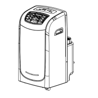
| Type | Portable |
| Noise Level (High) | 52 dB |