Do you have a question about the Ideal Air IAH24MD-D3DNA3D and is the answer not in the manual?
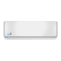
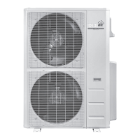
Provides an overview of Indoor Unit, Outdoor Unit, and Remote Controller models.
Lists the available models for the indoor and outdoor units with their part numbers.
Details technical specifications for cooling and heating performance.
Presents detailed technical data for both indoor and outdoor units.
Illustrates cooling and heating performance based on compressor speed.
Shows how cooling and heating capacity varies with outdoor temperature.
Provides data sheets for cooling and heating at rated frequency.
Displays noise levels for indoor and outdoor units at different operating speeds.
Shows the physical dimensions of the indoor and outdoor units.
Provides dimensional drawings and measurements for the indoor unit.
Provides dimensional drawings and measurements for the outdoor unit.
Illustrates the refrigerant flow and components in the system.
Covers electrical components, wiring, and PCB diagrams.
Shows the electrical connections and wiring layout for the unit.
Displays the printed circuit board layout for the indoor unit.
Explains the operational modes, functions, and remote controller usage.
Details the buttons and display icons of the remote controller.
Covers basic operation steps and remote controller battery replacement.
Describes the functionality of various modes like Auto, Cool, Dry, Fan, and Heating.
Provides important safety precautions and guidelines for installation.
Lists and illustrates the essential tools required for installation.
Covers the procedures and requirements for installing the air conditioner.
Shows the recommended clearances and mounting dimensions for installation.
Lists the components to be checked before installation begins.
Guides on choosing the optimal location for indoor and outdoor units.
Details the electrical safety and connection requirements for installation.
Step-by-step instructions for installing the indoor unit.
Step-by-step instructions for installing the outdoor unit.
Explains the process of vacuuming the system and detecting leaks.
Outlines post-installation checks and test operation procedures.
Covers routine maintenance, precautions, and troubleshooting.
Important safety warnings and steps before performing maintenance.
Lists error codes displayed by the unit and their meanings.
Provides diagnostic steps for common malfunctions.
Addresses issues related to overload and high discharge temperature.
Helps diagnose and resolve normal operational malfunctions.
| Brand | Ideal Air |
|---|---|
| Model | IAH24MD-D3DNA3D |
| Category | Air Conditioner |
| Language | English |