Classic Combi FF 280 - Installation
2
INTRODUCTION
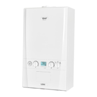
The new Classic Combi FF280 is a cast iron, balanced flue,
fanned gas boiler.
Central heating (CH) output is spot rated at 23.4 kW (80 000
Btu/h) with on/off thermostatic control and is suitable for use with
heating loads down to 4.4 kW (15 000 Btu/h).
Maximum instantaneous domestic hot water (DHW) output is
also 23.4kW (80 000 Btu/h).
The boiler is designed for use with fully pumped sealed water
systems but can also be connected to open water systems if
required.
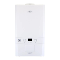
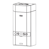
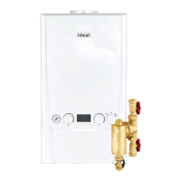
The boiler casing is of white enamelled mild steel with a
removable controls pod. A drop-down door gives access to the
control box.
Note. This boiler can only be used on fully pumped systems.
The boiler is supplied fully assembled, with a domestic hot water
calorifier, diverter valve, circulating pump, pressure gauge,
safety valve and CH expansion vessel (contained in a module
on top of the boiler).
Fixed temperature CH and DHW controls are fitted and the
boiler incorporates a DHW 'preheat' facility.
The module also includes a CH thermostatic valve and bypass.
No external bypass is required.
The domestic hot water and central heating pipe connections
may be made at the top or bottom of the boiler as required.
The boiler is supplied with a standard flue kit suitable for rear or
side outlet applications up to 600mm (23
1/2"). Optional extra
extension ducts up to 3m (118"), rear or side outlet, are
available.
Note. A Vertex Flue Kit with a side outlet may be used - see the
Vertex Flue Kit Installation Instructions for details.
OPERATION
Domestic Hot Water (DHW)
With no call for either DHW or CH the boiler will periodically fire
at low gas rate for a few seconds, in order to maintain the DHW
calorifier in a preheated condition.
Note. The DHW 'preheat' operates 24 hours a day unless an
external programmer is fitted, when it can be timed.
When there is demand for DHW the boiler fires at full gas rate,
the diverter valve remains de-energised and the full output from
the boiler is directed to the DHW calorifier, providing a maximum
DHW draw-off of 9.6 l/m (2.1 gpm) at 35° C. temperature rise.
At DHW draw-off rates below approximately 6 l/m (1.3 gpm) the
boiler reduces to low gas rate when the DHW temperature
reaches about 60°C and maintains the low draw-off
temperature between 50°C and 75°C. When the demand for
DHW is satisfied the 'preheat' cycle resumes, unless there is a
CH demand, which takes priority.
Central Heating (CH)
When there is demand for CH, the boiler fires at full output, to
supply the demand. The CH circuit within the module
incorporates a thermostatic valve which operates to maintain a
high boiler temperature during periods of cold CH start-up,
necessary for the instantaneous delivery of DHW , if there is a
demand at this time. Water is not released to the system until a
temperature of 60°C. is reached within the boiler.
Refer also to 'Boiler Water Circuit Diagrams'.
GENERAL
CONTENTS
Air Supply ..................................................................... 7
Boiler Clearances ......................................................... 6
Boiler Exploded View ................................................. 46
Burner Exploded View .............................................. .47
Control Box Exploded View ..................................... .47
Electrical Connections .............................................. 25
Electrical Regulations ................................................. 8
Extension Ducts - Fitting ........................................... 21
External Control ......................................................... 27
Fault Finding .............................................................. 48
Flueing .......................................................................... 7
Rear Installation ...................................................... 13
Side Installation ...................................................... 17
Gas Safety (Installation & Use)
Regulations, 1994 ........................................................ 5
Gas Supply ................................................................... 5
Health & Safety Document No 635 ............................. 5
Initial Lighting . .......................................................... 29
Installation .................................................................. 11
Mandatory Requirements ............................................ 5
Pump ........................................................................... 24
Servicing ..................................................................... 32
Short List of Parts ...................................................... 54
Spares Replacement .................................................. 35
Terminal Guards. .......................................................... 7
Thermostatic Radiator Valves. .................................... 8
Water Circuit Diagrams ............................................... 4
Water Connections .................................................... 24
Water Requirements .................................................... 7




 To Next Page