Do you have a question about the Ideal Boilers Mexico Super 4100 FF - 4125 FF and is the answer not in the manual?
Boiler specifications and technical data for models 4100 FF and 4125 FF.
Performance metrics like input, output, and efficiency for boiler models.
Details required for the Benchmark log book for installation and servicing records.
Details on optional kits like Extension Duct, Programmer, and Overheat Thermostat.
Compliance with current gas safety installation and use regulations in GB and IE.
Boiler suitability for direct hot water systems and use on sealed systems with an overheat thermostat.
Guidelines for locating the boiler, including floor mounting and specific building types.
Minimum space requirements around the boiler for operation and servicing.
Minimum gas pressure, pipe sizing, and testing requirements for installation.
Spacing requirements for flue terminals relative to openings and boundaries.
Ventilation requirements for boiler installation, especially in compartments.
Suitability for pumped systems, pipework recommendations, and venting requirements.
Guidance on water treatment and system flushing to prevent limescale and corrosion.
Recommendations for system controls, including TRVs and room thermostats for efficient operation.
Earthed connection, mains supply voltage, fuse rating, and isolation methods.
List and identification of components within the boiler assembly diagram.
List of items included in Pack A, including the boiler assembly and documentation.
List of items included in the standard flue pack (Pack B).
Step-by-step instructions for removing the boiler casing panels.
Method for calculating the required flue length based on boiler type and outlet.
Details of available flue kits and maximum extension duct lengths.
How to make system connections for fully pumped heating and DHW systems.
How to make connections for gravity DHW and pumped CH systems.
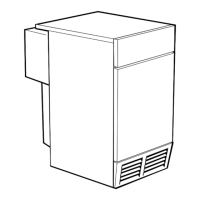
Step-by-step guide for assembling the rear flue outlet.
Steps for preparing the wall, including marking and cutting the flue hole.
Instructions for cutting the flue to length and fitting the boiler sealing ring.
Steps for fitting foam seal, flue assembly, locating boiler, and connecting flue.
Exploded view and steps for assembling the side flue outlet.
Instructions for preparing the wall for side flue installation, including hole cutting.
Steps for cutting the flue and fitting the boiler sealing ring for side outlet.
Instructions for fitting the foam seal for the side flue assembly.
Steps for fitting the flue assembly, side plates, locating boiler, and connecting flue.
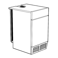
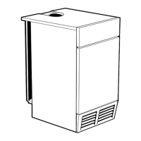
Exploded view and steps for top flue outlet assembly for 100 FF model.
Instructions for wall preparation and cutting the hole for top flue outlet.
Steps for cutting the flue and fitting the boiler sealing ring for top outlet.
Instructions for fitting the foam seal for the top flue assembly.
Steps for fitting flue assembly, side plates, locating boiler, and connecting flue.
Details of extension duct components and associated hardware.
Information on flue kits, maximum duct lengths, and support requirements.
Step-by-step instructions for fitting the flue extension kit.
Steps for positioning and securing the terminal wall plate.
Minimum gas pressure, pipe size, and testing for gas connection.
Connecting system flow and return pipework, including notes on pipe size and valves.
Minimum requirements for fully pumped systems, including pump position and water velocity.
Guidance on pipework design for gravity systems, including elbow limits and head/run calculations.
Requirements for mains supply, wiring, isolation, and earthing.
Flow and pictorial wiring diagrams, terminal strip connections, and lead securing.
Guidance on wiring external controls like time switches and thermostats.
Detailed pictorial wiring diagram for the boiler and its components.
Wiring diagram for a mid-position valve system.
Wiring diagram for systems with two spring closed valves.
Wiring diagram for gravity HW and pumped CH using Honeywell 'C' Plan.
How to wire a frost thermostat into the system for protection.
Step-by-step instructions for refitting the boiler casing panels.
Procedures for ensuring electrical safety and testing the gas installation.
Step-by-step guide for lighting the boiler and checking burner operation.
Checks for correct boiler operation, burner response, and system controls.
Procedures for checking system soundness, flushing, and balancing.
Explaining operation, safety, controls, and documentation to the householder.
Guidance on regular servicing, legal requirements, and pre-service checks.
Steps for removing boiler casing panels to access internal components for servicing.
Steps for removing the burner and controls assembly from the boiler.
Instructions for cleaning the burner head, injectors, and pilot assembly.
Steps for cleaning the fan, flue baffles, and heat exchanger.
Step-by-step guide for reassembling the boiler components in the correct order.
Procedures for adjusting pilot and main burner pressures after servicing.
Important safety notes and checks before replacing any boiler component.
Steps for replacing the sightglass assembly on the front plate.
Detailed steps for removing and refitting the pilot burner assembly.
Instructions for removing and replacing the control thermostat.
Steps for removing and refitting the boiler's control panel.
Instructions for replacing the overheat thermostat if fitted to the boiler.
Steps for replacing the ignition electrode and lead.
Detailed steps for removing and refitting the main burner.
Steps for replacing the main burner injector.
Instructions for replacing the gas valve, ensuring correct orientation and sealing.
Steps for removing and refitting the fan assembly.
Instructions for replacing the air pressure switch and connecting sensing tubes.
Steps for removing and refitting the printed circuit board (PCB).
A diagnostic flowchart to identify and resolve common boiler faults.
List of commonly required replacement parts with part numbers and product codes.
Visual representation of common replacement parts listed in the short list.
Exploded view and legend for the boiler control panel assembly.
Exploded view and legend for the PCB box assembly.
Exploded view and legend for the burner and controls assembly.
Exploded view and legend for the boiler casing assembly.
| Brand | Ideal Boilers |
|---|---|
| Model | Mexico Super 4100 FF - 4125 FF |
| Category | Boiler |
| Language | English |