- 17 -
A
B
C
D
E
•
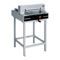
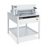
Operation
•
The measurement is set with the backgauge
crank.(A) The symbol – rotary direction –
moves to the right on the display (B) (see
picture C). The rotary direction of the
backgauge crank (A) is indicated on the right.
Keep turning the backgauge crank to the right
until a measurement appears (see picture E).
The reference position is reached.
The cutting size can now be set with the
handle (A).
If the backgauge is right at the front the
symbol – rotary direction – will move to the
left (see picture D). Turn the backgauge crank
to the left until the rotary direction appears on
the right
in the display (see picture C).
Afterwards turn the backgauge crank to the
right until a measurements appears (see
picture E). The reference position is reached.
The cutting size can now be set with the
handle (A). Proceed to position ! from the
rear.
Measurement is shown on the display in inches
or cm (B).
Information:
When the machine is only switched off by the
Key switch
G
(main switch
E
is still ON) it is
not necessary to advance to the reference
point when a new measurement is inserted.