SERVICING
71
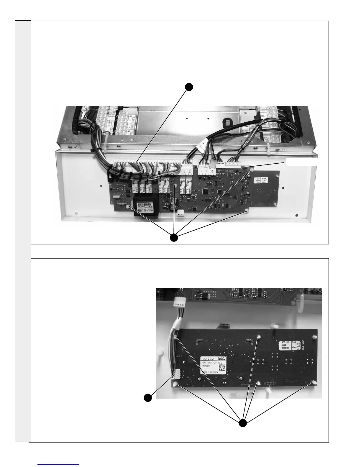
MAIN PCB REPLACEMENT
1. Refer to Frame 55.
2. Remove the upper front panel & put the control panel
into the service position. Refer to Frame 57.
3. Fit the earth strap provided with the spare PCB to
your wrist and to a suitable earthed metal.
4. Pull off all of the main PCB connectors.
5. Remove the four plastic nuts retaining the main PCB.
6. Fit new PCB and BCC (BCC must be tted or boiler
will not work) and re-assemble in reverse order.
7. Check the operation of the boiler. Refer to Frame 55.
4
72
USER INTERFACE BOARD
1. Refer to Frame 55.
2. Remove the upper front panel & put the control
panel into the service position. Refer to Frame
57.
3. Fit the earth strap provided with the spare PCB
to your wrist and to a suitable earthed metal.
4. Pull off all of the main PCB edge connectors
(refer to Frame 71).
5. Remove the four plastic nuts retaining the main
PCB - see item 5 in Frame 71.
6. Remove the main PCB.
7. Pull off the user interface edge connector.
8. Unclip the board and lift to clear the six
mounting posts.
9. Fit the new user interface.
10. Reassemble in reverse order.
10. Check the operation of the boiler. Refer to
Frame 55.
5
8
7
BCC tted here