10
Stripmaster
®
Model 954™ Permanent Gripper Wire Stripper
Your IDEAL Stripmaster
®
Model 954™ Permanent Gripper Wire Stripper has been aligned by IDEAL. After time, it may become necessary to realign.
The following section describes three different adjustments that are necessary to insure proper blade and clamp bar alignment.
Permanent Gripper Faceplate
Adjustments Permanent
Faceplate Vertical
1. Remove top plate and slug tray.
2. Close blades using set up switch at top of machine. It is helpful to
use a light source beneath the machine to illuminate the hole through the
blade and bushing. Visually check bushing and blade cutting holes for
proper alignment.
3. Adjust set screws (use 1/16” hex wrench) located near both side plates
approximately 3 1/2” from the face plate, to raise or lower all six blades to
their proper vertical position if needed. Adjust both sides evenly.
4. Install slug tray and top plate.
Adjustments Permanent Faceplate Horizontal
1. Remove slug tray.
2. Close blades using set up switch at top of machine. It is helpful to use a light source beneath the machine to illuminate the hole through the blade
and bushing. Visually check bushing and blade cutting holes for proper alignment.
3. By turning both front left and front right set screws (use 3/32 hex wrench), reposition the carriage left or right to obtain the proper alignment.
4. Install slug tray.
Adjustments Permanent Faceplate Clamp Bar
1. With air connected to machines, turn power off and remove slug tray.
2. To raise gap of the clamp bar, turn setscrews clockwise. To reduce gap of the clampbar, turn setscrews counter-clockwise.
3. Replace Slug tray.
Note: Over extending one or both setscrews may result in wire being “pulled” into the machine during the stripping action. Not enough setscrew adjustment
could result in an excessive amount of clamping force resulting in damage to outer insulation.
Service (Qualified personnel only; continued)
Alignment Adjustments (continued)
Adjustments Clamp Yoke Stop
1. With air connected to machine, turn power off and remove slug tray.
It is again helpful to use a light source positioned at or between blade and
trigger area to illuminate the hole through the blade and bushing.
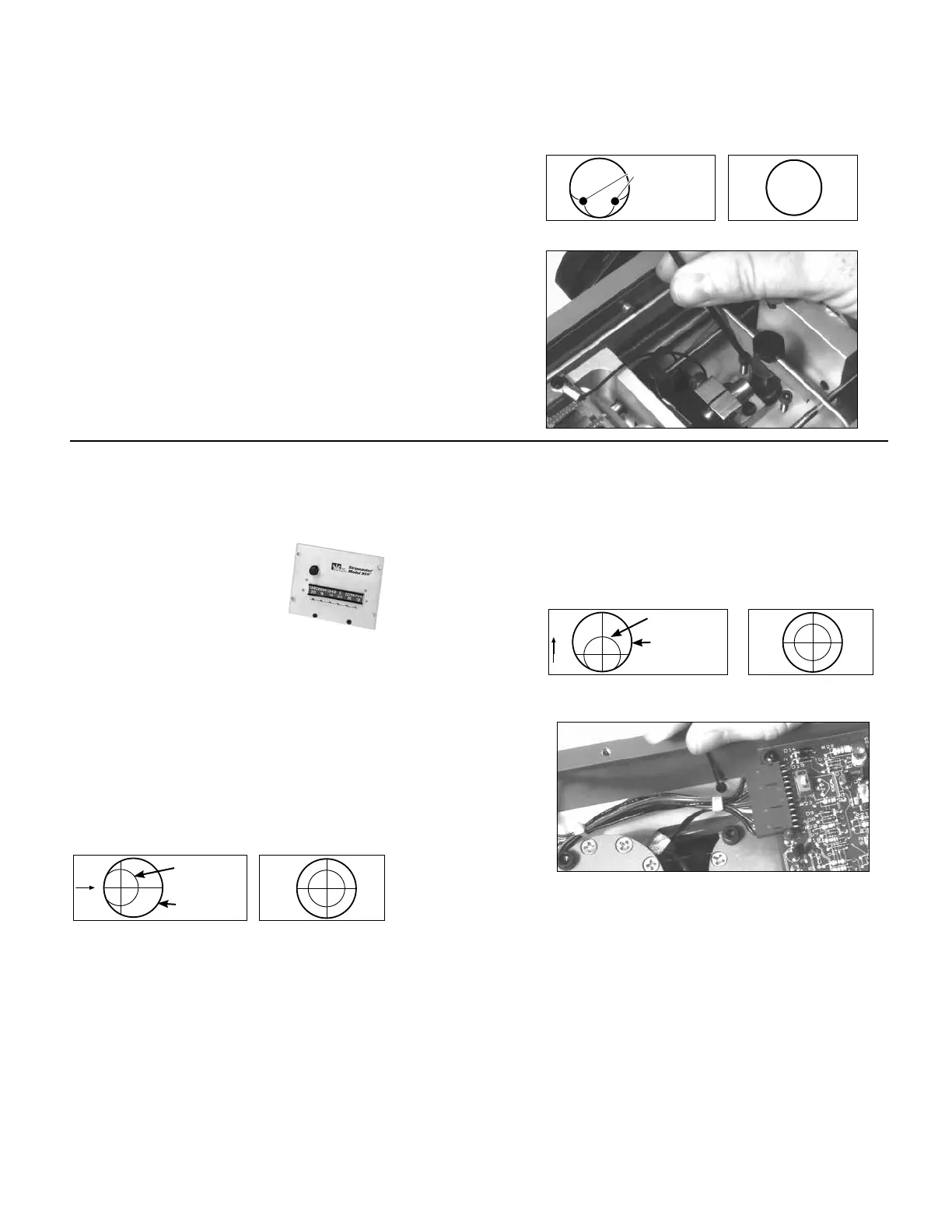
2. With blades in open position, look through all wire guides to see if blades are
obstructing the wire entry path. No part of the blade should be
visible.
3. If an adjustment is needed, disconnect the air supply and raise or lower clamp
yoke stop screws evenly (use 7/64 hex wrench). This will raise or lower blades,
thus ensuring a clear path for wire entry in all six bushings.
4. Insert slug tray.
INCORRECT CORRECT
BLADE EDGES
GUIDE HOLE
INCORRECT CORRECT
BLADE HOLE
GUIDE HOLE
INCORRECT CORRECT
BLADE HOLE
GUIDE HOLE