8
Service (Qualified personnel only; continued)
Circuit Board Adjustment
Strip Delay
Return Delay
It may be desirable to increase the time delay after cutting/gripping and
before pulling the slug off a wire. This will insure a more secure grip
and a better cut.
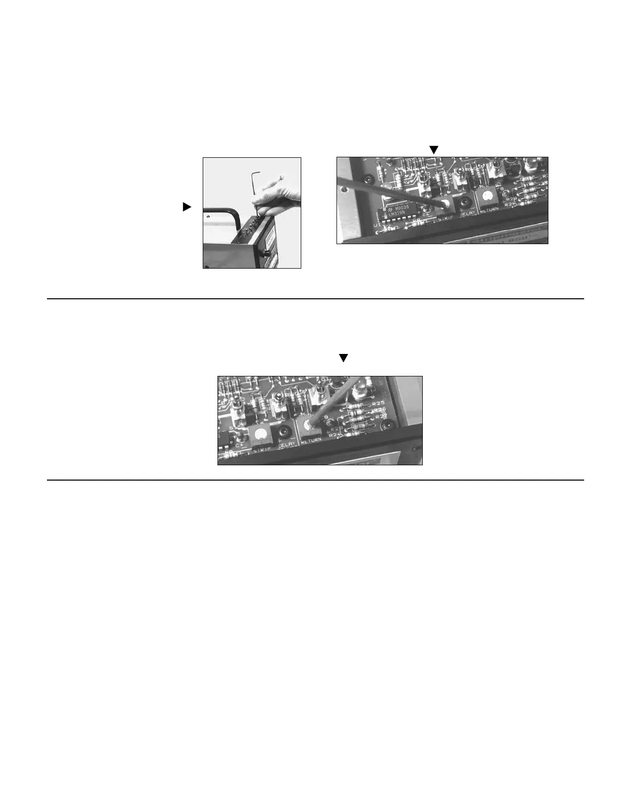
1. Remove the six #6-32 button head
cap screws (use 5/64 hex wrench)
and the top plate. Locate the circuit
board near the front of the unit.
2. Locate and adjust the “strip” delay by turning the potentiome-
ter screw with a small electronic screwdriver. Clockwise (+) to
increase delay and counterclockwise (-) to reduce delay.
3. Cycle the machine and continue to readjust as required.
4. Replace top plate.
It may be desired to increase the time delay after stripping a wire to
allow the operator more time to remove the wire before the unit resets
itself.
1. Remove the six #6-32 button head cap
screws (use 5/64 hex wrench) and the
top plate. Locate the circuit board near
the front of the unit.
2. Locate and adjust the “return” delay by turning the potentiom-
eter screw with a small electronic screwdriver. Clockwise (+) to
increase delay and counterclockwise (-) to reduce delay.
3. Cycle the machine and continue to read
just as required.
4. Replace top plate.