2: P
RODUCT
S
PECIFICATIONS
2-172 FC6A S
ERIES
MICROS
MART
U
SER
’
S
M
ANUAL
FC9Y-B1722
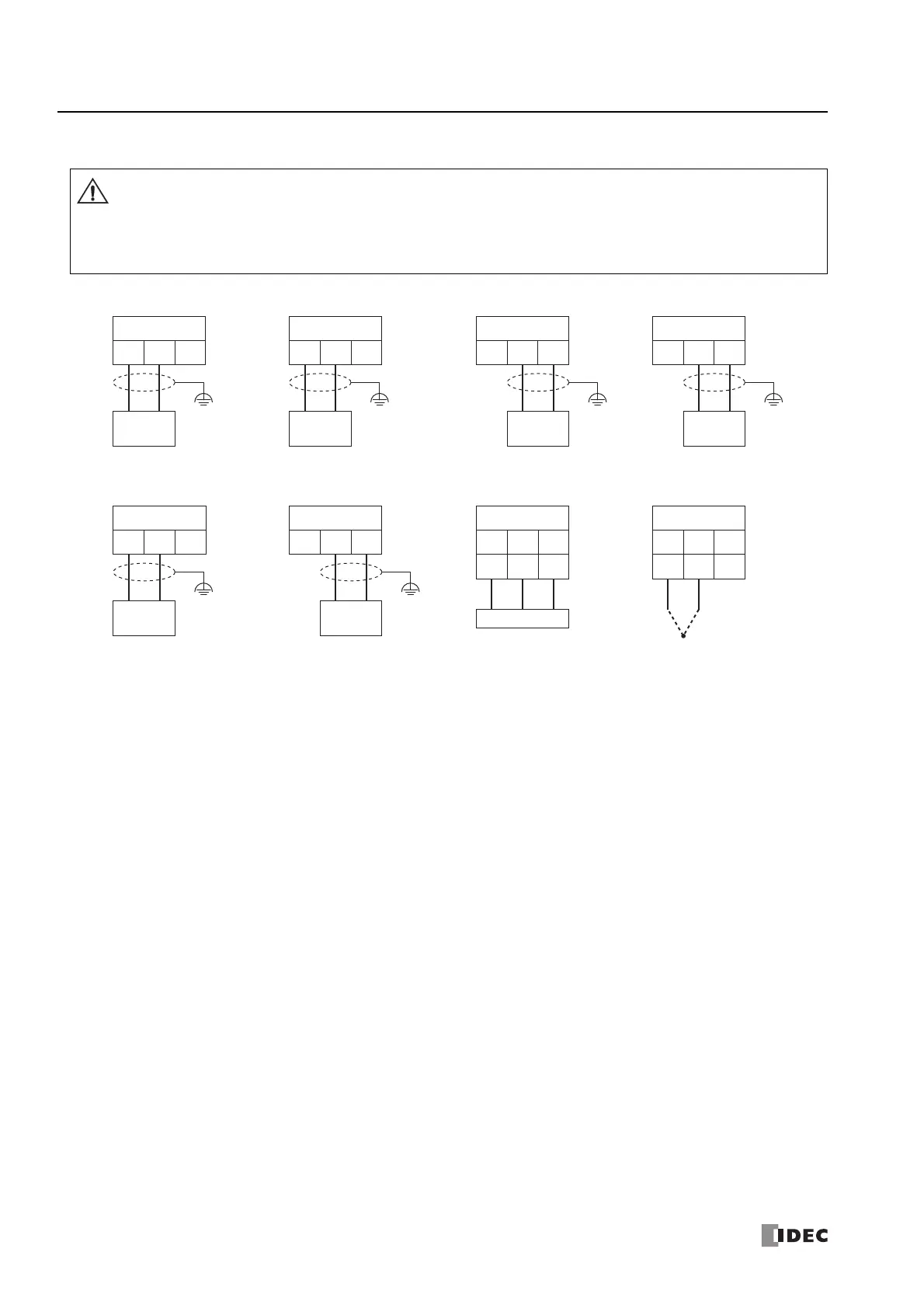
Wiring Arrangement and Wiring Examples
Do not connect a thermocouple to a part with hazardous voltage (60V DC or peak 42.4V DC or higher part).
Before turning on the power, please check that the wiring is correct. If the wiring is incorrect, the analog I/O cartridge
may be damaged. When the analog I/O cartridge may malfunction due to noise, wire it with a shielded cable and
connect both ends to the FE.
When connecting cables to the analog I/O cartridges, the tightening torque is 0.22 to 0.25 Nm.
Caution
FC6A-PK2AV FC6A-PK2AW
FC6A-PJ2A FC6A-PJ2CP
Analog Voltage Input Device
0 to 10 V
+–
OUT1
+–NC
Analog Voltage Input Device
0 to 10 V
+–
OUT0
+–NC
Analog Current Input Device
4 to 20 mA
–+
OUT0
NC – +
Analog Current Input Device
4 to 20 mA
+–
OUT1
NC +–
Analog Current Output Device
0 to 20 mA
4 to 20 mA
–+
IN1
+–+
Analog Voltage Output Device
0 to 10 V
+–
IN0
+–+
Thermocouple
Resistance Thermometer
Pt / Ni
A
BB’
IN0
ABB’
+–NC
+
–
IN1
ABB’
+–NC
 Loading...
