3: I
NSTALLATION
AND
W
IRING
3-6 FC6A S
ERIES
MICROS
MART
U
SER
’
S
M
ANUAL
FC9Y-B1722
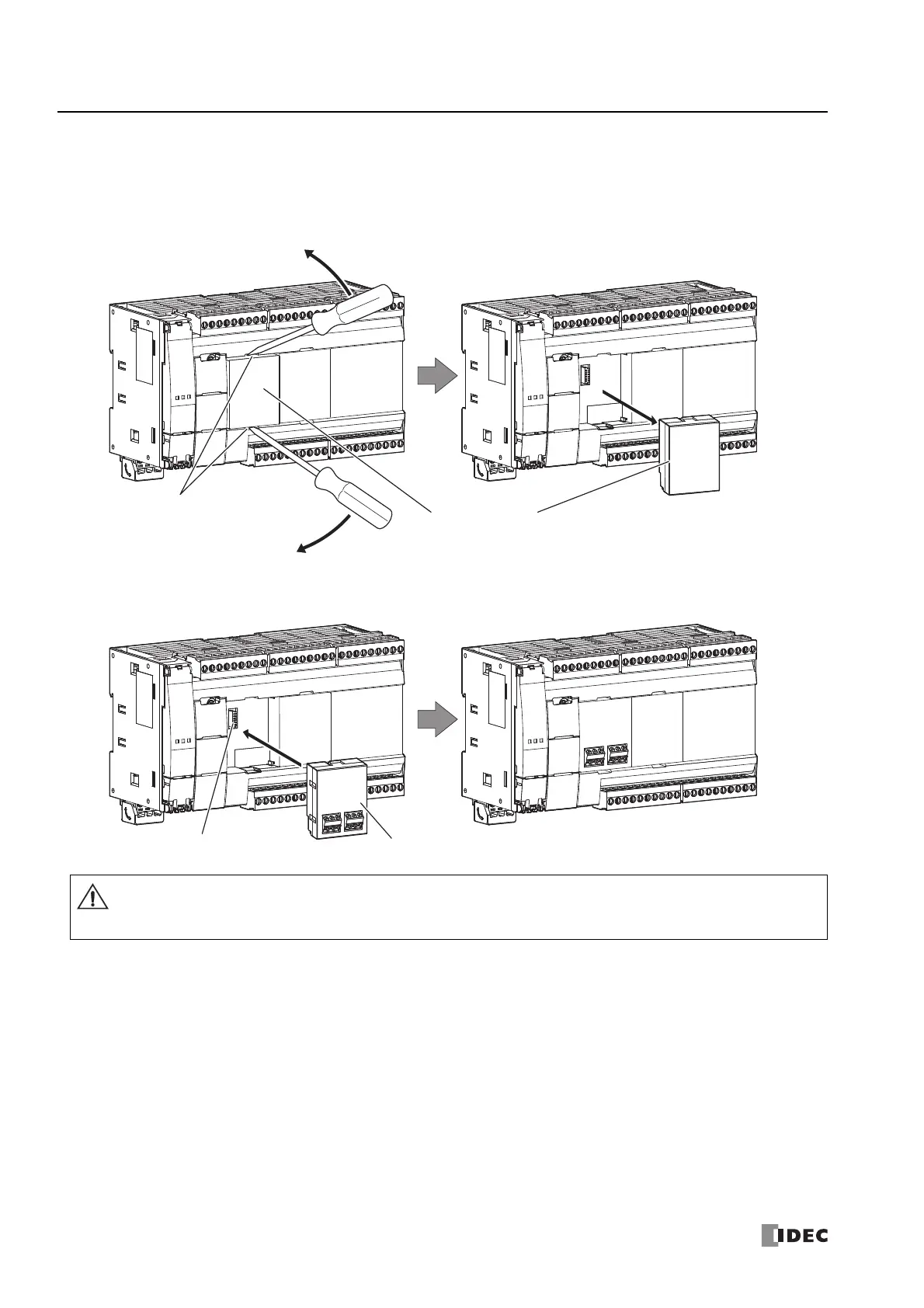
Assembling the CPU Module and a Cartridge
The following procedure describes the assembly of the CPU module (cartridge slot 1) and an analog I/O cartridge.
1. Insert a flathead screwdriver into each of the screwdriver slots (two locations) on the CPU module (cartridge slot 1) and
remove the dummy cartridge straight off the CPU module by pushing down the dummy cartridge tabs.
2. Take care with the vertical orientation of the analog I/O cartridge and firmly push the analog I/O cartridge connector onto
cartridge slot 1 on the CPU module.
Note: Cartridges cannot be attached to the Plus CPU module.
Dummy Cartridge
Screwdriver Slot
Analog I/O Cartridge
Cartridge Slot 1
Do not perform this work when the FC6A Series MICROSmart is powered. Otherwise there is a risk of damage.
Attach and remove the cartridge straight in relation to the CPU module. If you attach or remove the cartridge at an angle,
there is a risk of damage or communication failure.
Caution
 Loading...
