2: P
RODUCT
S
PECIFICATIONS
2-28 FC6A S
ERIES
MICROS
MART
U
SER
’
S
M
ANUAL
FC9Y-B1722
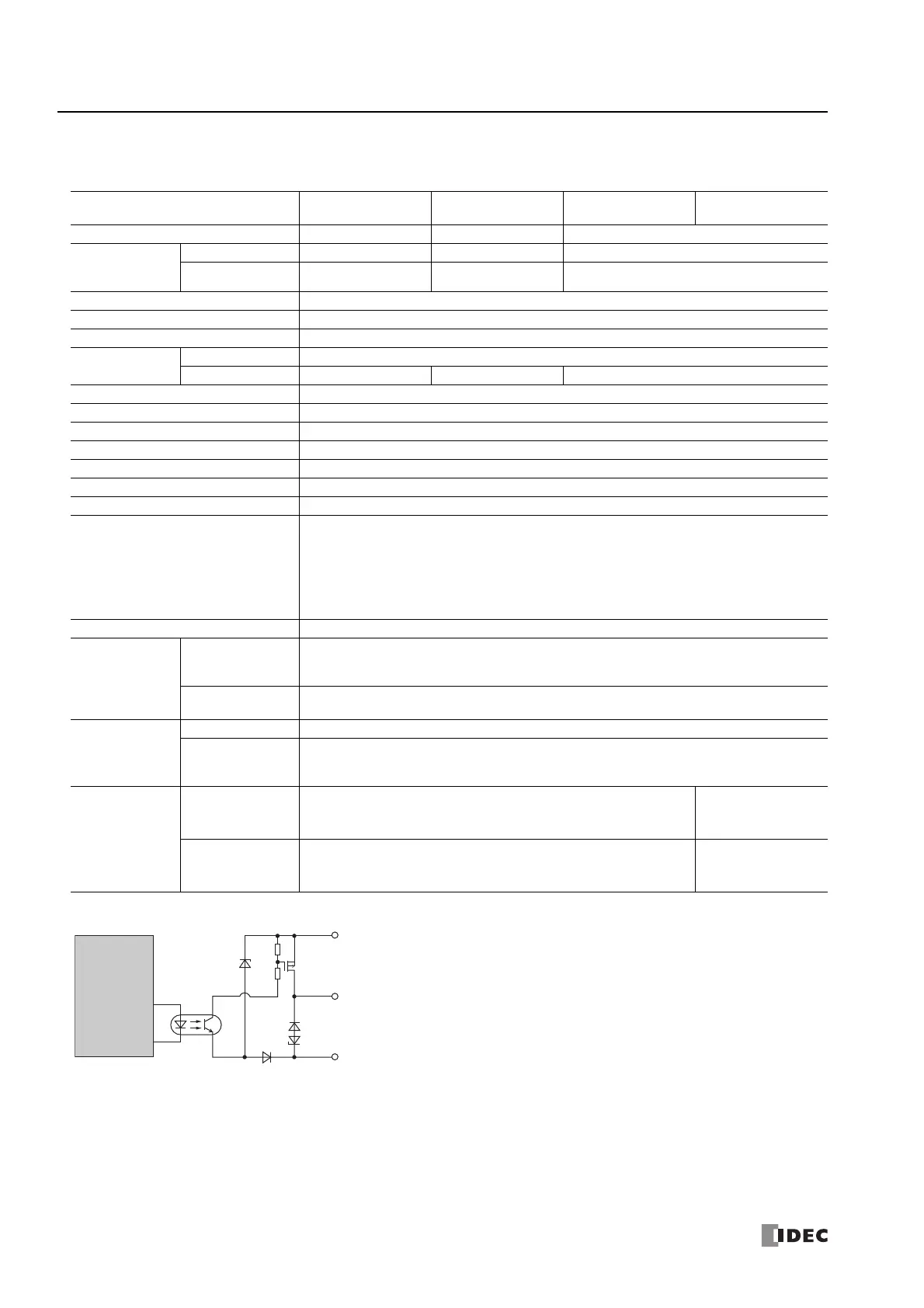
Transistor Protection Source Output Specifications
■ 24V DC power type
Output Internal Circuit (The overcurrent detection circuit has been omitted.)
Type No.
FC6A-C16P1CE
FC6A-C16P4CE
FC6A-C24P1CE
FC6A-C24P4CE
FC6A-C40P1CE
FC6A-C40P4CE
FC6A-C40P1CEJ
FC6A-C40P4CEJ
No. of Outputs 71016
Output Points
per Common
Line
COM0 7108
COM1 ――8
Rated Load Voltage 24V DC
Operating Load Voltage Range 20.4 to 28.8V DC
Terminal Arrangement See "24V DC Power Type" on page 2-37
Maximum Load
Current
1 0.5 A maximum
1 Common 3.5 A maximum 5 A maximum 4 A maximum
Voltage Drop (ON Voltage) 1 V or less, voltage between COM and output terminal when ON
Maximum Inrush Current 1 A
Leakage Current 0.1 mA maximum
Clamping Voltage 39 V±1 V
Maximum Lamp Load 12 W
Inductive Load L/R = 10 ms (28.8V DC, 1 Hz)
External Current Draw 100 mA maximum, 24V DC (-V terminal supply power)
Output Protection Functions
Overcurrent protection function (not a thermal shutdown function).
Overcurrent detected with 4 outputs as 1 group. (Group 1: Q0 to Q3, Group 2: Q4 to Q7, Group 3:
Q10 to Q13, Group 4: Q14 to Q17)
When overcurrent is detected, the 4 outputs in the corresponding group are turned off for a fixed
period (1 s). When overcurrent is detected, a special internal relay turns on (M8172 to M8175) and
the error LED [ERR] turns on.
Output Current Limit Value 1.0 to 2.0 A
Isolation
Between Output
Terminal and
Internal Circuit
Photocoupler isolated
Between Output
Terminals
Not isolated
I/O Terminal
Connector
Type See "24V DC Power Type" on page 2-37
Insertion/
Removal
Durability
100 times minimum
Output Delay
Turn ON Time
Q0 to Q1: 5 μs or less
Q2 to Q3: 30 μs or less
Q4 to Q7, Q10 to Q17: 300 μs or less
Q0 to Q7: 5 μs or less
Q10 to Q17: 300 μs or
less
Turn OFF Time
Q0 to Q1: 5 μs or less
Q2 to Q3: 30 μs or less
Q4 to Q7, Q10 to Q17: 300 μs or less
Q0 to Q7: 5 μs or less
Q10 to Q17: 300 μs or
less
V (
-
)
Output
COM (+)
Internal Circuit
 Loading...
