i-MARK 2 / i-MARK 3
USER MANUAL
VISIBILITY DELIVERED. PAGE 35 OF 55
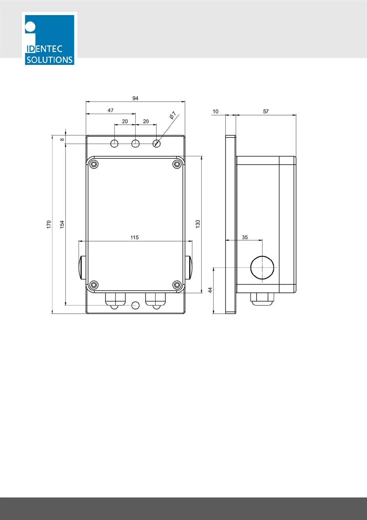
7.1.2 i-MARK 3
All dimensions in mm
Inside a protective housing (e.g. switch cabinet) or in a dust-free and completely dry environment the
i-MARK 3 can be mounted in every orientation. Outside a protective casing the i-MARK 3 must be
mounted in the orientation shown above with the cable inlets facing to the ground to protect dust and
moisture from entering the housing.
The i-MARK 3 is delivered with a set of 2 screws with plastic washers and pegs. These are intended to
mount the device to a concrete wall. Drill holes of 8 mm diameter for the pegs.
When mounting to other surfaces use appropriate mounting material.
Use at least 2 screws to mount the i-MARK 3!