Industrial Electronic Engineers, Inc.
SIZE
A
CODE IDENT NO.
05464
S03601-95B-40
Van Nuys, California
SCALE N/A
REV A
SHEET 10 of 14
08/26/02
4.8 Dedicated Hardware Lines
4.8.1 RESET
Hardware RESET is available on J1-14. Setting RESET low for greater than 50µS will clear the display and
set the cursor to the upper left character (power-up condition). Sinking current must be able to discharge a
1µF capacitor connected internally.
4.8. INTERRUPT (BUSY)
A busy signal is available on J1-1 and may be used to interrupt the host signaling a READY condition.
4.9 Self-Test
The display will go into self-test mode, if E2 is connected to the ground. In the self-test mode, the display will
display every printable character from 20 (HEX) to FF (HEX) until E2 is disconnected from ground.
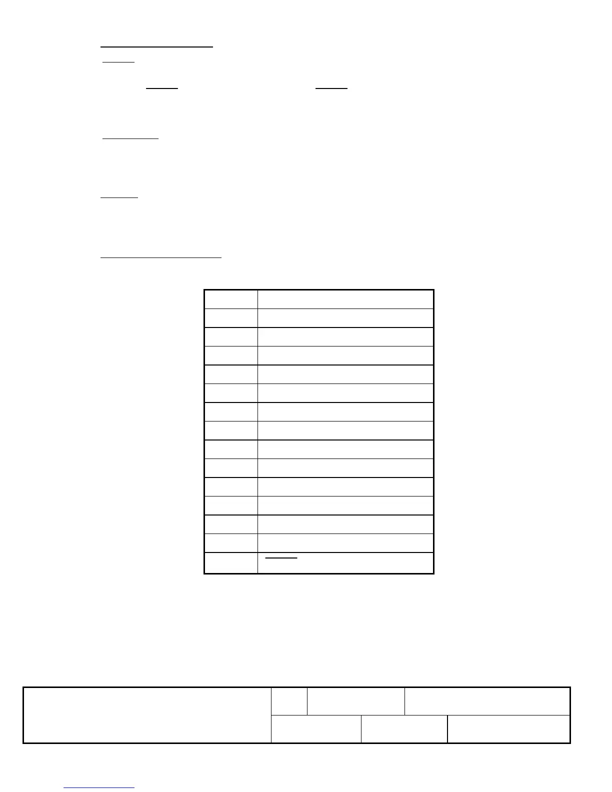
4.10 Connector Pin Assignments
J1 (POWER/DATA)
PIN NO. FUNCTION
J1-1 BUSY
J1-2 WRITE STROBE
J1-3 D7 (MSB)
J1-4 D6
J1-5 D5
J1-6 D4
J1-7 D3
J1-8 D2
J1-9 D1
J1-10 D0 (LSB)
J1-11 +5V @ 370mA (TYP) *
J1-12 GROUND (COMMON)
J1-13 NOT USED
J1-14
RESET
* For brightest software setting.
CMOS Note: Care must be taken to insure that input signals do not exceed the supply voltage or ground
levels. Data cables must be as short as possible to reduce signal overshoots.
 Loading...