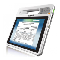
ICEFIRE2-T10 Mobile Clinic Assistant
Page ix
List of Figures
Figure 1-1: ICEFIRE2-T10...............................................................................................................2
Figure 1-2: Front Panel ..................................................................................................................4
Figure 1-3: Front Panel Buttons and Indicators..........................................................................5
Figure 1-4: Rear Panel....................................................................................................................6
Figure 1-5: Side Panels..................................................................................................................7
Figure 1-6: Top Panel.....................................................................................................................8
Figure 1-7: Bottom Panel...............................................................................................................8
Figure 1-8: Dimensions (units in mm)........................................................................................11
Figure 3-1: Release Battery Latches...........................................................................................18
Figure 3-2: Battery Installation....................................................................................................19
Figure 3-3: Lock the Battery........................................................................................................19
Figure 3-4: Battery Capacity Indicators .....................................................................................20
Figure 3-5: Windows 7 Power Management Screen .................................................................21
Figure 3-6: Insert Batteries to Docking Station.........................................................................22
Figure 3-7: SIM Card Slot Location.............................................................................................23
Figure 3-8: SIM Card Installation.................................................................................................23
Figure 3-9: Release the Stand .....................................................................................................25
Figure 3-10: Lock the Stand ........................................................................................................25
Figure 3-11: Secure the Holder ...................................................................................................26
Figure 3-12: Place the ICEFIRE2-T10 to the Docking Station ..................................................26
Figure 3-13: VESA Mounting Retention Screw Holes (Docking Station)................................27
Figure 3-14: LAN Connection......................................................................................................28
Figure 3-15: USB Device Connection .........................................................................................29
Figure 3-16: Smart Card Reader Installation .............................................................................29
Figure 3-17: Smart Card Reader Setting 1 .................................................................................30
Figure 3-18: Smart Card Reader Setting 2 .................................................................................31
Figure 3-19: Smart Card Reader Setting 3 .................................................................................31
Figure 3-20: Smart Card Reader Setting 4 .................................................................................32
Figure 3-21: Docking Station I/O Connectors............................................................................33
Figure 3-22: Serial Device Connector.........................................................................................34

 Loading...