Home
IEI Technology
Computer Hardware
WSB-H610
IEI Technology WSB-H610 - User Manual
187 pages
Manual
Specs
Ask a question
Save Page as PDF
To Next Page
To Next Page
Loading...
WSB-H610
PICMG 1.0 CPU Car
d
Page i
User Manual
MODEL:
WSB-H610
Full-Size PICMG 1.0 CPU Card Support
s 32nm LGA1
155 Intel®
Core™ i7/i5/i3/Pentium®/Celeron® CPU, Intel® H61 Chip
set,
DDR3, VGA/DVI-D, Dual Realtek PCIe GbE, USB 2.0, COM,
SA
T
A
3Gb/s, HD
Audio and RoHS
Rev
. 1.02 – 25
April, 2014
2
Table of Contents
Main Page
Default Chapter
4
Table of Contents
4
1 Introduction
16
Introduction
17
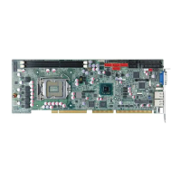
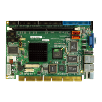
Figure 1-1: WSB-H610
17
Model Variations
18
Features
18
Table 1-1: WSB-H610 Model Variations
18
Connectors
19
Figure 1-2: Connectors
19
Dimensions
20
Figure 1-3: WSB-H610 Dimensions (MM)
20
Figure 1-4: External Interface Panel Dimensions (MM)
21
Data Flow
22
Figure 1-5: Data Flow Diagram
22
Technical Specifications
23
Table 1-2: WSB-H610 Specifications
24
2 Packing List
25
Anti-Static Precautions
26
Unpacking Precautions
26
Packing List
27
Optional Items
28
Table 2-1: Packing List
28
Table 2-2: Optional Items
30
3 Connectors
31
Peripheral Interface Connectors
32
WSB-H610 Layout
32
Figure 3-1: Connectors and Jumpers
32
External Interface Panel Connectors
33
Table 3-1: Peripheral Interface Connectors
33
Internal Peripheral Connectors
34
ATX Power Supply Enable Connector
34
Figure 3-2: ATX Power Supply Enable Connector Location
34
Table 3-2: Rear Panel Connectors
34
Table 3-3: ATX Power Supply Enable Connector Pinouts
34
Audio Kit Connector
35
Figure 3-3: Audio Connector Location
35
Table 3-4: Audio Connector Pinouts
35
Battery Connector
36
Figure 3-4: Battery Connector Location
36
Table 3-5: Battery Connector Pinouts
36
CPU Power Input Connector
37
DDR3 DIMM Slots
37
Figure 3-5: ATX Power Connector Pinout Location
37
Table 3-6: ATX Power Connector Pinouts
37
Digital I/O Connector
38
Figure 3-6: DDR3 DIMM Slot Locations
38
Figure 3-7: Digital I/O Connector Location
38
DVI-D Connector (DVI Model Only)
39
Figure 3-8: DVI-D Connector Location
39
Table 3-7: Digital I/O Connector Pinouts
39
EC SPI Flash Connector
40
Figure 3-9: EC SPI Flash Connector Location
40
Table 3-8: DVI-D Connector Pinouts
40
Table 3-9: EC SPI Flash Connector Pinouts
40
Fan Connector (CPU)
41
Floppy Disk Drive Connector
41
Figure 3-10: CPU Fan Connector Location
41
Table 3-10: CPU Fan Connector Pinouts
41
Figure 3-11: Floppy Disk Connector Location
42
Table 3-11: Floppy Disk Connector Pinouts
42
Front Panel Connector
43
Figure 3-12: Front Panel Connector Location
43
Table 3-12: Front Panel Connector Pinouts
43
I2C Connector
44
Infrared Interface Connector
44
Figure 3-13: I2C Connector Location
44
Table 3-13: I2C Connector Pinouts
44
Keyboard/Mouse Connector
45
Figure 3-14: Infrared Connector Location
45
Figure 3-15: Keyboard/Mouse Connector Location
45
Table 3-14: Infrared Connector Pinouts
45
Parallel Port Connector
46
Figure 3-16: Parallel Port Connector Location
46
Table 3-15: Keyboard/Mouse Connector Pinouts
46
Pcie Mini Card Slot
47
Figure 3-17: Pcie Mini Card Slot Location
47
Table 3-16: Parallel Port Connector Pinouts
47
SATA 3Gb/S Drive Connectors
48
Table 3-17: Pcie Mini Card Slot Pinouts
48
Serial Port Connectors, RS-232
49
Figure 3-18: SATA 3Gb/S Drive Connector Location
49
Table 3-18: SATA 3Gb/S Drive Connector Pinouts
49
Serial Port Connector, RS-422/485
50
Figure 3-19: Serial Port Connector Location
50
Table 3-19: Serial Port Connector Pinouts
50
Smbus Connector
51
Figure 3-20: RS-422/485 Connector Location
51
Table 3-20: RS-422/485 Connector Pinouts
51
Table 3-21: DB-9 RS-422/485 Pinouts
51
SPI ROM Connector
52
Figure 3-21: Smbus Connector Location
52
Figure 3-22: SPI ROM Connector Location
52
Table 3-22: Smbus Connector Pinouts
52
TPM Connector
53
Figure 3-23: TPM Connector Location
53
Table 3-23: SPI ROM Connector Pinouts
53
USB Connectors
54
Figure 3-24: USB Connector Pinout Locations
54
Table 3-24: TPM Connector Pinouts
54
Table 3-25: USB Port Connector Pinouts
54
External Peripheral Interface Connector Panel
55
Ethernet Connectors
55
Figure 3-25: External Peripheral Interface Connector
55
Figure 3-26: Ethernet Connector
55
Table 3-26: LAN Pinouts
55
Keyboard/Mouse Connector
56
Figure 3-27: PS/2 Pinout and Configuration
56
Table 3-27: Connector Leds
56
Table 3-28: Keyboard Connector Pinouts
56
USB Connector
57
VGA Connector
57
Table 3-29: USB Port Pinouts
57
Figure 3-28: VGA Connector
58
Table 3-30: VGA Connector Pinouts
58
4 Installation
59
Anti-Static Precautions
60
Installation Considerations
60
Socket LGA1155 CPU Installation
62
Figure 4-1: Disengage the CPU Socket Load Lever
62
Figure 4-2: Remove Protective Cover
63
Figure 4-3: Insert the Socket LGA1155 CPU
64
Figure 4-4: Close the Socket LGA1155
64
Socket LGA1155 Cooling Kit Installation
65
Figure 4-5: Cooling Kit Support Bracket
65
DIMM Installation
66
Figure 4-6: DIMM Installation
66
Jumper Settings
67
AT/ATX Power Select Jumper
67
Table 4-1: Jumpers
67
Clear CMOS Jumper
68
Figure 4-7: AT/ATX Power Mode Jumper Location
68
Figure 4-8: Clear BIOS Jumper Location
68
Table 4-2: AT/ATX Power Mode Jumper Settings
68
Table 4-3: Clear BIOS Jumper Settings
68
Wake-On LAN Jumper
69
Figure 4-9: Wake-On LAN Jumper Location
69
Table 4-4: Wake-On LAN Jumper Settings
69
Table 4-5: Wake-On LAN Jumper Pinouts
69
Chassis Installation
70
Airflow
70
CPU Card Installation
70
Internal Peripheral Device Connections
70
Dual RS-232 Cable with Slot Bracket
70
DVI-D/USB Kit Installation (DVI Model Only)
71
Figure 4-10: Dual RS-232 Cable Installation
71
SATA Drive Connection
72
Figure 4-11: DVI-D/USB Kit Installation
72
Figure 4-12: SATA Drive Cable Connection
73
USB Cable (Dual Port) with Slot Bracket
74
Figure 4-13: SATA Power Drive Connection
74
Pcie Mini Card Installation
75
Figure 4-14: Dual USB Cable Connection
75
External Peripheral Interface Connection
76
LAN Connection
76
Figure 4-15: Pcie Mini Card Installation
76
USB Device Connection (Single Connector)
77
Figure 4-16: LAN Connection
77
VGA Monitor Connection
78
Figure 4-17: USB Device Connection
78
Figure 4-18: VGA Connector
79
5 Bios
80
Introduction
81
Starting Setup
81
Using Setup
81
Getting Help
82
Unable to Reboot after Configuration Changes
82
BIOS Menu Bar
82
Table 5-1: BIOS Navigation Keys
82
Main
83
BIOS Menu 1: Main
83
Advanced
84
ACPI Settings
85
BIOS Menu 2: Advanced
85
BIOS Menu 3: ACPI Configuration
85
Trusted Computing
86
BIOS Menu 4: TPM Configuration
86
CPU Configuration
87
BIOS Menu 5: CPU Configuration
87
CPU Information
88
BIOS Menu 6: CPU Configuration
88
SATA Configuration
89
BIOS Menu 7: SATA Configuration
89
Intel TXT(LT) Configuration
90
BIOS Menu 8: Intel TXT(LT) Configuration
90
USB Configuration
91
BIOS Menu 9: USB Configuration
91
Super IO Configuration
92
BIOS Menu 10: Super IO Configuration
92
Floppy Disk Controller Configuration
93
Serial Port N Configuration
93
BIOS Menu 11: Serial Port N Configuration Menu
93
BIOS Menu 12: Serial Port N Configuration Menu
94
Parallel Port Configuration
98
BIOS Menu 13: Parallel Port Configuration Menu
98
H/W Monitor
99
BIOS Menu 14: H/W Monitor
100
CPU_FAN 1 Configuration
101
BIOS Menu 15: FAN 1 Configuration
101
Serial Port Console Redirection
102
BIOS Menu 16: Serial Port Console Redirection
102
Iei Feature
104
Chipset
105
BIOS Menu 17: IEI Feature
105
Northbridge Configuration
106
BIOS Menu 18: Chipset
106
BIOS Menu 19:Northbridge Chipset Configuration
106
Southbridge Configuration
109
BIOS Menu 20: Southbridge Chipset Configuration
109
Integrated Graphics
110
BIOS Menu 21: Integrated Graphics
110
Boot
111
BIOS Menu 22: Boot
111
Security
113
BIOS Menu 23: Security
113
Exit
114
BIOS Menu 24:Exit
114
6 Software Drivers
116
Available Software Drivers
117
Software Installation
117
Figure 6-1: Introduction Screen
118
Figure 6-2: Available Drivers
118
Chipset Driver Installation
119
Figure 6-3: Chipset Driver Screen
119
Figure 6-4: Chipset Driver Welcome Screen
120
Figure 6-5: Chipset Driver License Agreement
120
Figure 6-6: Chipset Driver Read Me File
121
Figure 6-7: Chipset Driver Setup Operations
121
Graphics Driver Installation
122
Figure 6-8: Chipset Driver Installation Finish Screen
122
Figure 6-9: Graphics Driver Welcome Screen
123
Figure 6-10: Graphics Driver License Agreement
123
Figure 6-11: Graphics Driver Setup Operations
124
Figure 6-12: Graphics Driver Installation Finish Screen
124
Lan Driver Installation
125
Figure 6-13: LAN Driver Welcome Screen
125
Figure 6-14: LAN Driver Installation
126
Figure 6-15: LAN Driver Installation Complete
126
Audio Driver Installation
127
Figure 6-16: Audio Driver - Extracting Files
127
Figure 6-17: Audio Driver Installation Welcome Screen
128
Figure 6-18: Audio Driver Installation
128
Figure 6-19: Audio Driver Installation Complete
128
ABIOS Options
129
B One Key Recovery
132
One Key Recovery Introduction
133
B.1 O Ne K Ey R Ecovery I Ntroduction
133
Figure B-1: IEI One Key Recovery Tool Menu
133
System Requirement
134
Supported Operating System
135
Setup Procedure for Windows
136
B.2 S Etup P Rocedure for W Indows
136
Create Partitions
137
Hardware and BIOS Setup
137
Figure B-2: Launching the Recovery Tool
138
Figure B-3: Recovery Tool Setup Menu
138
Figure B-4: Command Mode
139
Figure B-5: Partition Creation Commands
140
Install Operating System, Drivers and Applications
141
Build-Up Recovery Partition
142
Figure B-6: Launching the Recovery Tool
142
Figure B-7: Manual Recovery Environment for Windows
142
Figure B-8: Building the Recovery Partition
143
Figure B-9: Press any Key to Continue
143
Create Factory Default Image
144
Figure B-10: Press F3 to Boot into Recovery Mode
144
Figure B-11: Recovery Tool Menu
144
Figure B-12: about Symantec Ghost Window
145
Figure B-13: Symantec Ghost Path
145
Figure B-14: Select a Local Source Drive
146
Figure B-15: Select a Source Partition from Basic Drive
146
Figure B-16: File Name to Copy Image to
147
Figure B-17: Compress Image
147
Figure B-18: Image Creation Confirmation
148
Figure B-19: Image Creation Complete
148
Figure B-20: Image Creation Complete
148
Auto Recovery Setup Procedure
149
Figure B-21: Press any Key to Continue
149
B.3 a Uto R Ecovery S Etup P Rocedure
149
Figure B-22: Auto Recovery Utility
150
Figure B-23: Disable Automatically Restart
150
Figure B-24: Launching the Recovery Tool
151
Figure B-25: Auto Recovery Environment for Windows
151
Figure B-26: Building the Auto Recovery Partition
152
Figure B-27: Factory Default Image Confirmation
152
Figure B-28: Image Creation Complete
153
Figure B-29: Press any Key to Continue
153
Setup Procedure for Linux
154
BIOS Menu 25: IEI Feature
154
B.4 S Etup P Rocedure for L Inux
154
Figure B-30: Partitions for Linux
155
Figure B-31: System Configuration for Linux
156
Figure B-32: Access Menu.lst in Linux (Text Mode)
156
B.5 R Ecovery T Ool F Unctions
157
Figure B-34: Recovery Tool Main Menu
158
Factory Restore
159
Figure B-35: Restore Factory Default
159
Figure B-36: Recovery Complete Window
159
Backup System
160
Figure B-37: Backup System
160
Figure B-38: System Backup Complete Window
160
Figure B-39: Restore Backup
161
Figure B-40: Restore System Backup Complete Window
161
Restore Your Last Backup
161
Figure B-41: Symantec Ghost Window
162
Manual
162
Figure B-33: Recovery Tool Menu
157
Recovery Tool Functions
157
Restore Systems from a Linux Server through Lan
163
B.6 R Estore S Ystems from a L Inux S Erver through Lan
163
Configure DHCP Server Settings
164
Configure TFTP Settings
165
Configure One Key Recovery Server Settings
166
Create Shared Directory
167
Start the DHCP, TFTP and HTTP
167
Setup a Client System for Auto Recovery
168
Figure B-42: Disable Automatically Restart
169
Other Information
171
Using AHCI Mode or Ali M5283 / VIA VT6421A Controller
171
B.7 O Ther I Nformation
171
System Memory Requirement
173
C Terminology
174
D Digital I/O Interface
178
Introduction
179
Dio Connector Pinouts
179
Assembly Language Samples
179
Enable the DIO Input Function
179
Table 6-1: Digital I/O Connector Pinouts
179
D.1 I Ntroduction
179
Enable the DIO Output Function
180
Wsb-H610
180
E Watchdog Timer
181
F Hazardous Materials Disclosure
184
Hazardous Materials Disclosure Table for IPB Products Certified as Rohs Compliant under 2002/95/EC Without Mercury
185
Need help?
Do you have a question about the IEI Technology WSB-H610 and is the answer not in the manual?
Ask a question
IEI Technology WSB-H610 Specifications
General
Brand
IEI Technology
Model
WSB-H610
Category
Computer Hardware
Language
English
Related product manuals
IEI Technology WEB-6580
66 pages
IEI Technology WAFER-TGL-U
86 pages
IEI Technology ROCKY-3786EV
147 pages
IEI Technology ROCKY-4786EVG
180 pages
IEI Technology ROCKY-4786EV
145 pages
IEI Technology PCISA-LX
214 pages
DRPC-140-EHL Series
128 pages