Do you have a question about the IEI Technology ROCKY-4786EV and is the answer not in the manual?
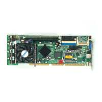
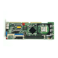
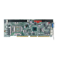
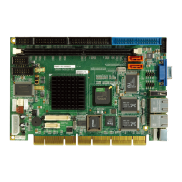
Overview of the PICMG 1.0 form factor ROCKY-4786EV/EVG Pentium 4 CPU platform.
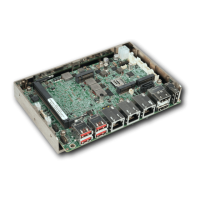
Details on the various connectors present on the ROCKY-4786EV/EVG CPU board.
Specifies the physical dimensions of the ROCKY-4786EV/EVG CPU board.
Illustrates the data flow between onboard chipsets and components on the CPU board.
Guidelines for preventing electrostatic discharge (ESD) damage to the CPU board.
Steps to follow when unpacking the ROCKY-4786EV/EVG to ensure proper handling.
Lists all components included with the ROCKY-4786EV/EVG CPU card.
Details on the locations and types of peripheral interface connectors on the CPU board.
Descriptions of connectors located internally on the ROCKY-4786EV/EVG CPU board.
Description of connectors found on the rear panel of the ROCKY-4786EV/EVG for external device connections.
Essential precautions, including ESD handling, to prevent damage during installation.
Important notices and considerations that must be read and understood before beginning installation.
Detailed steps for installing the ROCKY-4786EV/EVG CPU card onto the backplane.
Configuration options using jumpers on the ROCKY-4786EV/EVG board.
Instructions for connecting internal peripheral devices to the onboard connectors.
Connecting external devices to the ROCKY-4786EV/EVG's peripheral interface.
Instructions for installing system drivers from the provided CD.
Introduction to the BIOS setup program and its role in system configuration.
Overview of the main menu and available configuration options within the BIOS utility.
Configuration options for basic system settings like date, time, and IDE devices.
Settings for configuring IDE channels, including auto-detection and master/slave modes.
Options for configuring advanced system settings related to CPU and peripherals.
Details on configuring CPU features and hard disk boot priority.
Configuration options for CPU thermal management and related features.
Settings for configuring advanced chipset features, including DRAM timings.
Details on DRAM timing selectable, CAS latency, and precharge delays.
Settings for configuring integrated peripherals like IDE, USB, Audio, and LAN.
Configuration options for the OnChip IDE device, including block mode and PIO/UDMA settings.
Settings for onboard devices such as USB, Audio, and LAN controllers.
Configuration options for USB controllers, audio, and LAN devices.
Settings for the SuperIO device, including power-on functions and serial ports.
Options for power-on function, passwords, hot keys, and onboard controllers.
Settings for managing system power consumption and sleep states.
Configuration for power supply type, ACPI functions, and suspend states.
Settings for Plug and Play devices and PCI slot configurations.
Options for PNP OS installation, reset configuration, and resource control.
Displays system operating parameters like temperature, voltages, and fan speeds.
Configuration for auto-detecting DIMM/PCI clock and spread spectrum settings.
Introduction to the DIO connector and its interface with the Super I/O chipset.
Table detailing the pin assignments for the DIO connector and Super I/O GPIO port.
Assembly language examples for enabling digital I/O input and output functions.
Details on using BIOS INT 15H to set the watchdog timer period and trigger resets.
Table listing I/O address ranges and their corresponding system controllers or devices.
Map of memory addresses from 0 to 1MB, including system memory, VGA, and BIOS areas.
Table showing Interrupt Request (IRQ) assignments for system devices.
Table detailing the assignments of Direct Memory Access (DMA) channels.
Table listing hazardous substances and their presence in product parts per China RoHS.
| Form Factor | Mini-ITX |
|---|---|
| CPU Socket | LGA 1151 |
| Chipset | Intel H110 |
| Max Memory | 32GB |
| Dimensions | 170mm x 170mm |
| CPU | Intel Core i7/i5/i3 |
| Memory Speed | 2133MHz |
| Storage Interface | SATA III |
| Expansion Slots | 1 x PCIe x16 |
| Ethernet | Gigabit Ethernet |
| Serial Ports | 2 x RS-232/422/485 |
| Parallel Ports | 1 |
| Audio | HD Audio |
| Display Output | 1 x HDMI, 1 x VGA |
| Operating Temperature | -20°C ~ 60°C |
| Power Input | 12V DC |