ROCKY-4786EV/EVG User Manual
Page 43
PIN
DESCRIPTION PIN DESCRIPTION
1 TXD+ 8
GND
2 TXD- 9 GRN+
3 RXD+ 10 GRN-
4 CT_TXD 11 YEL-
5 CT_RXD 12 YEL+
6 RXD- 13 S GND
7 N/C 14 S GND
Table 3-16: RJ-45 Ethernet Connector Pinouts
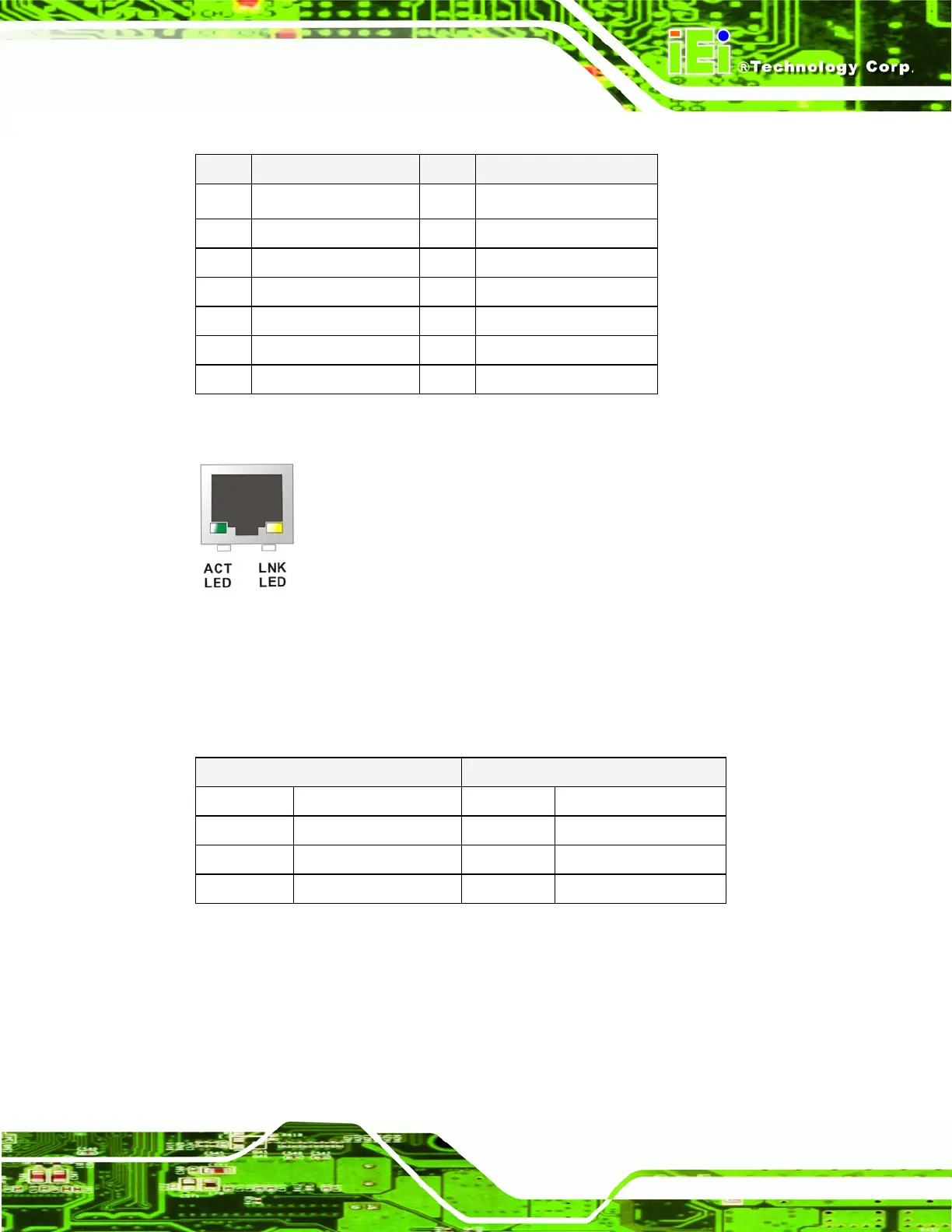
Figure 3-16: RJ-45 Ethernet Connector
The RJ-45 Ethernet connector has two status LEDs, one green and one yellow. The green
LED indicates activity on the port and the yellow LED indicates the port is linked. See
Table 3-17.
SPEED LED ACT/LINK LED
STATUS
DESCRIPTION STATUS DESCRIPTION
OFF 10 Mbps connection OFF No link
ORANGE 100 Mbps connection YELLOW Linked
GREEN 1 Gbps connection BLINKING Date activity
Table 3-17: RJ-45 Ethernet Connector LEDs
3.3.3 LINE OUT Connector
Connect an audio device to the line out connector on the rear panel Figure 3-14 (labeled
number 3).
 Loading...