14
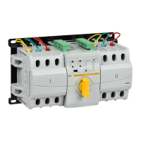
Ðèñóíîê / Figure 1
I
II
UI
UII
ON
ON
MANU
I
II
T
T
UN=0
UN=1
T1
T2
0
10
20
30
0
10
20
30
5
6
8
4
2
1
3
7
1 – èíäèêàòîð íàëè÷èÿ íàïðÿæåíèÿ îñíîâíîãî ââîäà / voltage detector
of primary input;
2 – èíäèêàòîð íàëè÷èÿ íàïðÿæåíèÿ ðåçåðâíîãî ââîäà / voltage detector
of reserve input;
3 – ðåãóëÿòîð óñòàíîâêè âðåìåíè çàäåðæêè ïåðåêëþ÷åíèÿ ïèòàíèÿ ñ
îñíîâíîãî ââîäà íà ðåçåðâíûé / regulator for setting the delay time for
switching power from the main input to the backup;
4 – èíäèêàòîð ïîëîæåíèÿ ãëàâíîé êîíòàêòíîé ãðóïïû âñòðîåííîãî
àâòîìàòè÷åñêîãî âûêëþ÷àòåëÿ îñíîâíîãî ââîäà / position indicator of the main
contact group of the integral circuit breaker of the primary input;
5 – èíäèêàòîð ïîëîæåíèÿ ãëàâíîé êîíòàêòíîé ãðóïïû âñòðîåííîãî
àâòîìàòè÷åñêîãî âûêëþ÷àòåëÿ ðåçåðâíîãî ââîäà / position indicator of the
main contact group of the integral circuit breaker of the reserve input;
6 – ïåðåêëþ÷àòåëü ñ àâòîìàòè÷åñêîãî ðåæèìà ðàáîòû íà ðó÷íîé /
switch from automatic to manual operation mode;
7 – ðåãóëÿòîð óñòàíîâêè âðåìåíè çàäåðæêè ïåðåêëþ÷åíèÿ ñ
ðåçåðâíîãî ââîäà íà îñíîâíîé / regulator for setting the delay time for switching
from backup to primary input;
8 – ðóêîÿòêà ðó÷íîãî ïåðåêëþ÷åíèÿ / manual switch handle
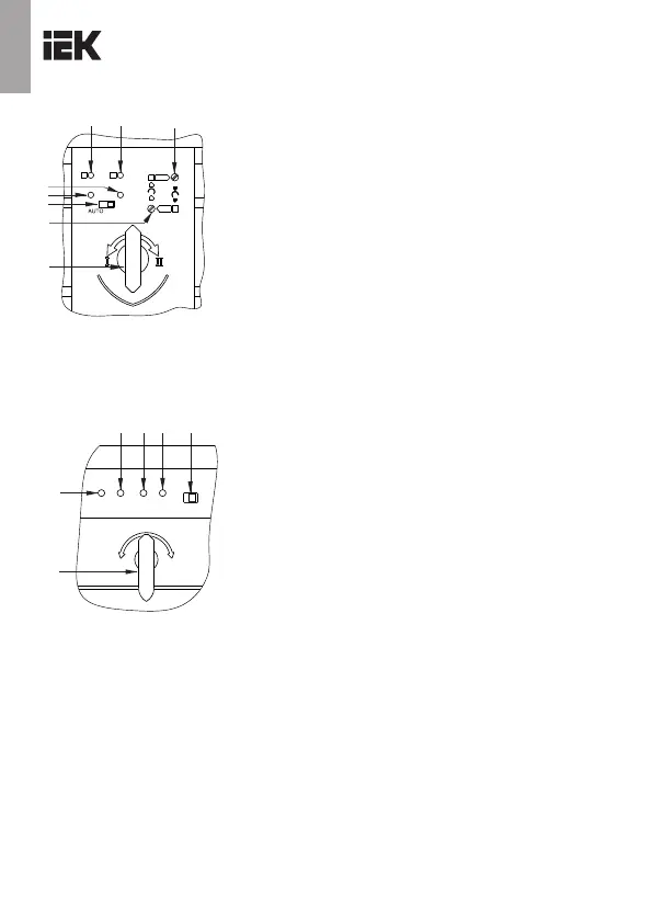
Ðèñóíîê / Figure 2
AC
ON
ONAC
AUTO MANU
I
II
1
2 3
4 5
6
I
II
0
1 – èíäèêàòîð íàëè÷èÿ íàïðÿæåíèÿ íà îñíîâíîì ââîäå / voltage detector of
primary input;
2 – èíäèêàòîð ïîëîæåíèÿ ãëàâíîé êîíòàêòíîé ãðóïïû âñòðîåííîãî
àâòîìàòè÷åñêîãî âûêëþ÷àòåëÿ îñíîâíîãî ââîäà / position indicator of the main
contact group of the integral circuit breaker of the primary input;
3 – èíäèêàòîð íàëè÷èÿ íàïðÿæåíèÿ ðåçåðâíîãî ââîäà / voltage detector of
reserve input;
4 – èíäèêàòîð ïîëîæåíèÿ ãëàâíîé êîíòàêòíîé ãðóïïû âñòðîåííîãî
àâòîìàòè÷åñêîãî âûêëþ÷àòåëÿ ðåçåðâíîãî ââîäà / position indicator of the main
contact group of the integral circuit breaker of the reserve input;
5 - ïåðåêëþ÷àòåëü ñ àâòîìàòè÷åñêîãî ðåæèìà ðàáîòû íà ðó÷íîé / switch
from automatic to manual operation mode;
6 – ðóêîÿòêà ðó÷íîãî ïåðåêëþ÷åíèÿ / manual switch handle
KARAT
 Loading...