Tilt-Bed Trailers 4
LOADING & UNLOADING
The trailer should be positioned on level ground.
Except in emergencies, loading and unloading should be carried
out with the trailer attached to the towing vehicle. If for any reason
you have to do so with the trailer detached, take great care to
ensure that the jockey wheel is securely clamped and the
handbrake is fully applied before proceeding. If the trailer is on soft
ground it may be necessary to provide additional support under the
jockey wheel to prevent it from sinking into the ground.
TILTING THE TRAILER BODY
CT166G, CT167G, CT166GA, CT167GA (Fenner Electric Pump)
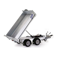
The tilting system comprises an electro-hydraulic pump (fig 1)
powered by an on-board heavy duty 12V battery to operate a pair
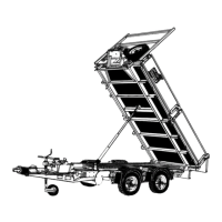
of hydraulic rams. The pump is operated from a remote control
switch pad on a detachable lead (fig 2). An isolator switch with
removable key is also provided to isolate the on-board electrical
system.
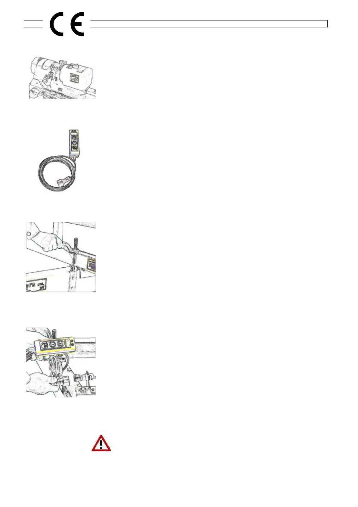
Operation
Before commencing tilting operations, the screw/clamps securing
the "A"-frame to the tilting platform should be released (see Fig.3)
Connect the remote control lead to the socket on the side of the
pump. (fig 4) Insert the key into the isolator switch and turn
clockwise through 90
o
to switch on.
After checking that the rear of the trailer is clear, operate the 'up
arrow' button on the remote control to tilt the trailer platform. To
ensure that the platform cannot be accidentally tilted, disconnect
the remote control lead plug from the socket (a straight pull).
To return the tilting platform to the horizontal position, ensure that
the area between the platform and chassis is clear of obstructions
and operate the 'down arrow' button until the platform is fully
lowered. Turn the isolator key anti-clockwise through 90
o
to switch
off the system, and remove the key.
During normal operation the 'Green' LED lamp on the remote
control will be lit. If the 'Red' LED lamp lights it will indicate that the
battery charge is low -See pages 6-7 for battery information and
more on control indicators.
ENSURE THAT THE SCREW/CLAMPS ARE IN THE LOCKED
POSITION AND THE ISOLATOR KEY HAS BEEN REMOVED
BEFORE DRIVING AWAY.
Fig.3
Fig.2
Fig.1
Fig.4