MAINTENANCE 9VX3
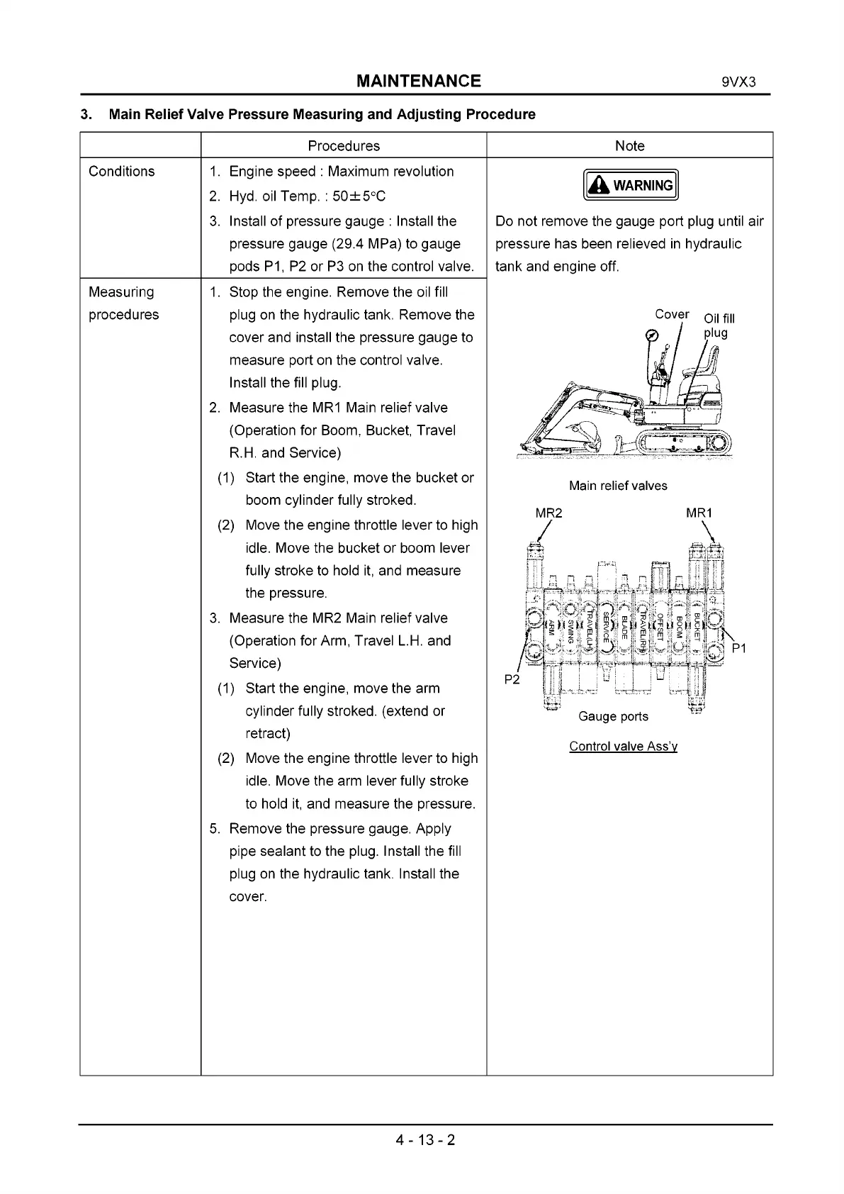
3. Main Relief Valve Pressure Measuring and Adjusting Procedure
Procedures Note
Conditions 1. Engine speed : Maximum revolution
2. Hyd. oil Temp. : 50±5°C
3. Install of pressure gauge : Install the
pressure gauge (29.4 MPa) to gauge
pods P1, P2 or P3 on the control valve.
A WARNING
Do not remove the gauge port plug until air
pressure has been relieved in hydraulic
tank and engine off.
Cover 0N А,,
Main relief valves
MR2 MR1
/ \
43s 43*43?
M ' * p |
'f !>*|м |»<|м !м 1^ -■<
P2 {!; - * -
1
« r — ^ J
.ЦЦД*ч мС'р
Gauge ports
Control valve Ass’v
Measuring
procedures
1. Stop the engine. Remove the oil fill
plug on the hydraulic tank. Remove the
cover and install the pressure gauge to
measure port on the control valve.
Install the fill plug.
2. Measure the MR1 Main relief valve
(Operation for Boom, Bucket, Travel
R.H. and Service)
(1) Start the engine, move the bucket or
boom cylinder fully stroked.
(2) Move the engine throttle lever to high
idle. Move the bucket or boom lever
fully stroke to hold it, and measure
the pressure.
3. Measure the MR2 Main relief valve
(Operation for Arm, Travel L.H. and
Service)
(1) Start the engine, move the arm
cylinder fully stroked, (extend or
retract)
(2) Move the engine throttle lever to high
idle. Move the arm lever fully stroke
to hold it, and measure the pressure.
5. Remove the pressure gauge. Apply
pipe sealant to the plug. Install the fill
plug on the hydraulic tank. Install the
cover.
4-13-2
 Loading...