MAINTENANCE 9VX3
4. Over load Relief Valve Pressure Measuring and Adjusting Procedure
Procedures Note
Conditions
Measuring
procedures
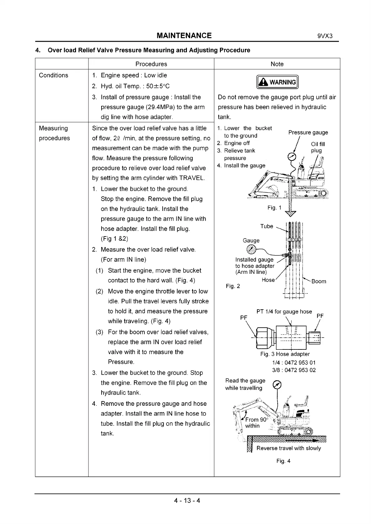
1. Engine speed : Low idle
2. Hyd. oil Temp. : 50±5°C
3. Install of pressure gauge : Install the
pressure gauge (29.4MPa) to the arm
dig line with hose adapter.
Since the over load relief valve has a little
of flow, 2& /min, at the pressure setting, no
measurement can be made with the pump
flow. Measure the pressure following
procedure to relieve over load relief valve
by setting the arm cylinder with TRAVEL.
1. Lower the bucket to the ground.
Stop the engine. Remove the fill plug
on the hydraulic tank. Install the
pressure gauge to the arm IN line with
hose adapter. Install the fill plug.
(Fig 1 &2)
2. Measure the over load relief valve.
(For arm IN line)
(1) Start the engine, move the bucket
contact to the hard wall. (Fig. 4)
(2) Move the engine throttle lever to low
idle. Pull the travel levers fully stroke
to hold it, and measure the pressure
while traveling. (Fig. 4)
(3) For the boom over load relief valves,
replace the arm IN over load relief
valve with it to measure the
Pressure.
3. Lower the bucket to the ground. Stop
the engine. Remove the fill plug on the
hydraulic tank.
4. Remove the pressure gauge and hose
adapter. Install the arm IN line hose to
tube. Install the fill plug on the hydraulic
tank.
A WARNING
Do not remove the gauge port plug until air
pressure has been relieved in hydraulic
tank.
1. Lower the bucket
to the ground
2. Engine off
3. Relieve tank
pressure
4. Install the gauge
Pressure gauge
Installed gauge
to hose adapter
(Arm IN line)
Hose
Fig. 2
Boom
Fig. 3 Hose adapter
1/4 : 0472 953 01
3/8 : 0472 953 02
Read the gauge
while travelling
0
s r n
, ^From 90'
- \ within
A ^
Reverse travel with slowly
Fig. 4
4-13-4
 Loading...