MAINTENANCE 9VX3
5. Swing Relief Valve Pressure Measuring and Adjusting Procedure
Procedures Note
Conditions
Measuring
procedures
Adjusting
procedures
1. Engine speed : Low idle
2. Hyd. oil Temp. : 50±5°C
3. Install of pressure gauge : Install the
pressure gauge (29.4 MPa) to the P2
gauge port.
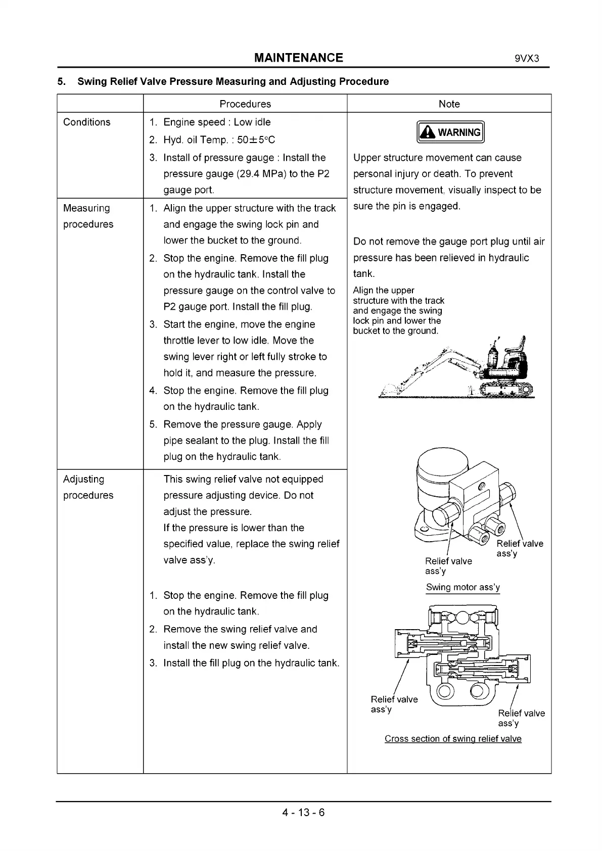
1. Align the upper structure with the track
and engage the swing lock pin and
lower the bucket to the ground.
2. Stop the engine. Remove the fill plug
on the hydraulic tank. Install the
pressure gauge on the control valve to
P2 gauge port. Install the fill plug.
3. Start the engine, move the engine
throttle lever to low idle. Move the
swing lever right or left fully stroke to
hold it, and measure the pressure.
4. Stop the engine. Remove the fill plug
on the hydraulic tank.
5. Remove the pressure gauge. Apply
pipe sealant to the plug. Install the fill
plug on the hydraulic tank.
This swing relief valve not equipped
pressure adjusting device. Do not
adjust the pressure.
If the pressure is lower than the
specified value, replace the swing relief
valve ass’y.
1. Stop the engine. Remove the fill plug
on the hydraulic tank.
2. Remove the swing relief valve and
install the new swing relief valve.
3. Install the fill plug on the hydraulic tank.
A WARNING
Upper structure movement can cause
personal injury or death. To prevent
structure movement, visually inspect to be
sure the pin is engaged.
Do not remove the gauge port plug until air
pressure has been relieved in hydraulic
tank.
Align the upper
structure with the track
and engage the swing
lock pin and lower the
bucket to the ground.
Swing motor ass’y
Cross section of swing relief valve
4-13-6
 Loading...