9VX3
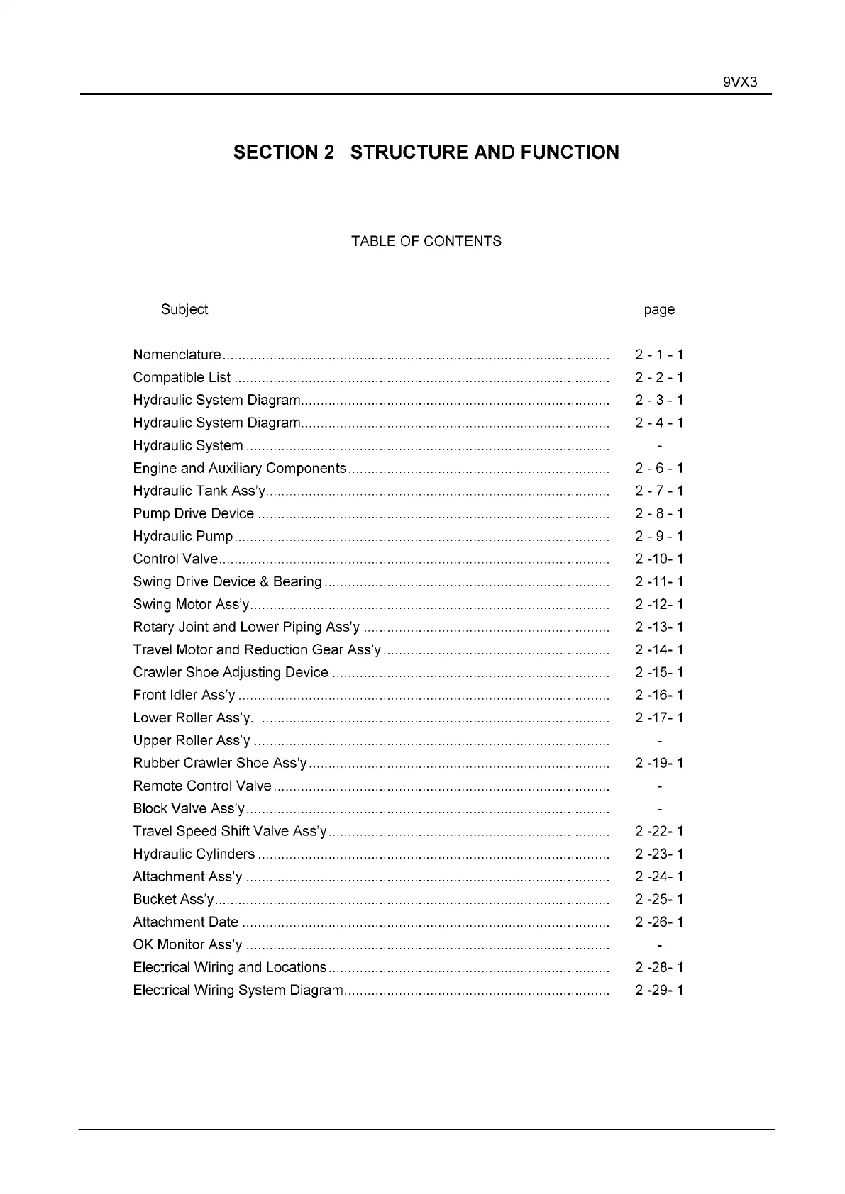
SECTION 2 STRUCTURE AND FUNCTION
TABLE OF CONTENTS
Subject page
Nomenclature
............................................................................................................
2-1-1
Compatible L ist
.........................................................................................................
2 - 2 - 1
Hydraulic System Diagram
......................................................................................
2-3-1
Hydraulic System Diagram
......................................................................................
2-4-1
Hydraulic System
.....................................................................................................
Engine and Auxiliary Components
.........................................................................
2-6-1
Hydraulic Tank Ass’y
................................................................................................
2-7-1
Pump Drive Device
..................................................................................................
2-8-1
Hydraulic Pump
.........................................................................................................
2-9-1
Control Valve
.............................................................................................................
2-10-1
Swing Drive Device & Bearing
...............................................................................
2-11-1
Swing Motor Ass’y
....................................................................................................
2-12-1
Rotary Joint and Lower Piping Ass’y
....................................................................
2-13-1
Travel Motor and Reduction Gear Ass’y
...............................................................
2-14-1
Crawler Shoe Adjusting Device
.............................................................................
2-15-1
Front Idler Ass’y
........................................................................................................
2-16-1
Lower Roller Ass’y
....................................................................................................
2-17-1
Upper Roller Ass’y
...................................................................................................
Rubber Crawler Shoe Ass’y
....................................................................................
2-19-1
Remote Control Valve
..............................................................................................
Block Valve Ass’y
.....................................................................................................
Travel Speed Shift Valve Ass’y
..............................................................................
2 -2 2 - 1
Hydraulic Cylinders
..................................................................................................
2 -23-1
Attachment Ass’y
.....................................................................................................
2 -24-1
Bucket Ass’y
..............................................................................................................
2 -25-1
Attachment D ate
.......................................................................................................
2 -26-1
OK Monitor Ass’y
.....................................................................................................
Electrical Wiring and Locations
..............................................................................
2 -28-1
Electrical Wiring System Diagram
..........................................................................
2 -29-1
 Loading...