STRUCTURE AND FUNCTION 9VX3
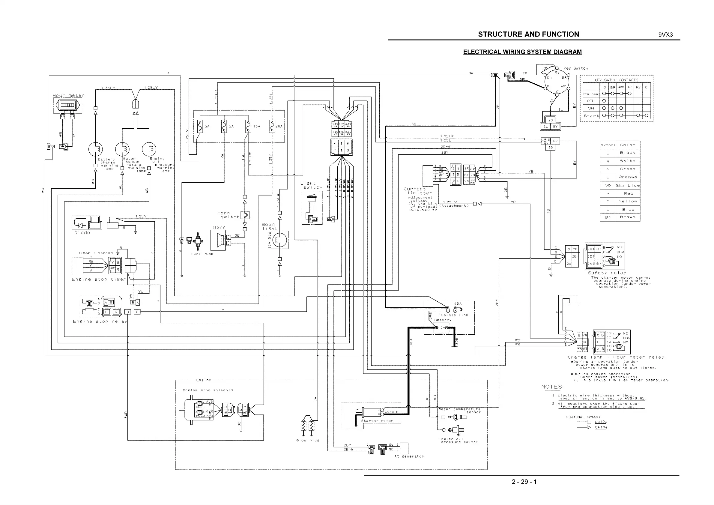
ELECTRICAL WIRING SYSTEM DIAGRAM
<ey Swi tch
KEY SWTCH CONTACTS
в
BR
ACC
Ri R2
c
эре-heat
OFF
О
ON
о
-o-
-o
S ta rt 4> -o
Symbo i
Color
В
Black
W
Wh i te
G
Green
О
Oran g e
Sb
Sky blue
R
Red
Y
Ye I Iow
L
В I ue
Br
Brown
The starter motor cannot
operate during engine
operation (under power
generation).
С D
( В b-p' N C
( E >—o C O M
E
( a )
--
о NO
, - N /XJOOCN
A В
Charge lamp ■ Hour m eter relay
•©During an operation (under
power generation), it is
charge lamp putting out lights.
i®During engine operation
(under Power gen era tio n ),
it is a foxtail millet meter operation.
Electric wire thickness without
special mention is set to AVS-Q.85.
AiI couplers show the figure seen
from the connection side side.
2- 29-1