MICROWAVE HOOD COMBINATION
INSTALLATIONINSTRUCTIONS
This product is suitable for use above electric or gas cooking products up to and including 36" (91.4 cm) wide. See "Installation
Requirements" section for further notes.
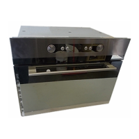
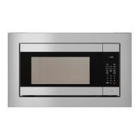
These installation instructions cover different models. The appearance of your particular model may differ slightly from the illustration in
these installation instructions.
INSTRUCTIONS.D'INSTALLATION
DEL'ENSEMBLEFOURA MICRO-ONDES/HOTTE
Ce produit est con£;u pour I'utilisation au-dessus d'appareils de cuisson electriques ou & gaz de 36" (91,4 cm) de largeur ou moins. Voir
la section "Exigences d'installation" pour d'autres remarques.
Ces instructions d'installation sont valables pour plusieurs modeles. II se peut que I'apparence de votre propre modele soit legerement
differente de celle montree sur les illustrations dans ce document.
Table of Contents / Tabledes mati@res
MICROWAVE HOOD COMBINATION SAFETY ....................... 1
INSTALLATION REQUIREMENTS ............................................ 2
Tools and Parts .......................................................................2
Remove Cardboard Template ................................................ 2
Location Requirements ........................................................... 2
Product Dimensions ................................................................ 3
Electrical Requirements .......................................................... 3
INSTALLATION INSTRUCTIONS .............................................. 4
Remove Mounting Plate .......................................................... 4
Rotate Blower Motor ............................................................... 4
Locate Wall Stud(s) ................................................................. 6
Mark Rear Wall ........................................................................ 7
Drill Holes in Rear Wall ............................................................ 7
Attach Mounting Plate to Wall ................................................ 8
Prepare Upper Cabinet ........................................................... 8
Install Damper Assembly ........................................................ 9
Install the Microwave Oven ..................................................... 9
Complete Installation ........................................................... 10
VENTING DESIGN SPECIFICATIONS ................................... 11
ASSISTANCE ........................................................................... 12
Replacement Parts ............................................................... 12
Accessories .......................................................................... 12
SECURITE DE L'ENSEMBLE FOUR A MICRO-ONDES/HO'I-rE ......... 13
EXIGENCES D'INSTALLATION ......................................................... 13
Outillage et pieces ........................................................................... 13
Depose du gabarit de carton .......................................................... 14
Exigences d'emplacement .............................................................. 14
Dimensions du produit .................................................................... 14
Specifications electriques ............................................................... 15
INSTRUCTIONS [:)'INSTALLATION .................................................. 15
Depose de la plaque de montage ................................................... 15
Reorientation du moteur du ventilateur .......................................... 15
Identifier la position du/des poteau(x) du colombage mural .......... 17
Trace sur lemur arriere ................................................................... 18
Pergage de trous dans lemur arriere .............................................. 19
Fixation de la plaque de montage sur lemur ................................. 19
Preparation du placard mural .......................................................... 20
Installation du module du clapet anti-reflux .................................... 20
Installation du four & micro-ondes .................................................. 21
Achever I'installation ........................................................................ 22
SPECIFICATIONS DU CIRCUIT D'EVACUATION ........................... 23
ASSISTANCE ...................................................................................... 24
Pieces de rechange ......................................................................... 24
Accessoires ..................................................................................... 24
MICROWAVE HOOD COMBINATION SAFETY
Your safety and the safety of others are very important.
We have provided many important safety messages in this manual and on your appliance. Always read and obey all safety
messages.
This is the safety alert symbol.
This symbol alerts you to potential hazards that can kill or hurt you and others.
All safety messages will follow the safety alert symbol and either the word "DANGER" or "WARNING."
These words mean:
You can be killed or seriously injured if you don't immediately
follow instructions.
You can be killed or seriously injured if you don't follow
instructions.
All safety messages will tell you what the potential hazard is, tell you how to reduce the chance of injury, and tell you what can
happen if the instructions are not followed.
W10344701 B