hipot.com 62
Then press the Test button on the front panel. The tester will begin outputting high voltage on the output connectors.
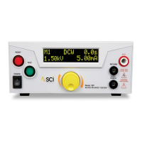
Then the display will show a value similar to that of the standard.
Turn and press the rotary knob to enter the reading of the standard AC Ammeter into the tester. Once all digits are entered
the tester will advance to the next calibration point.
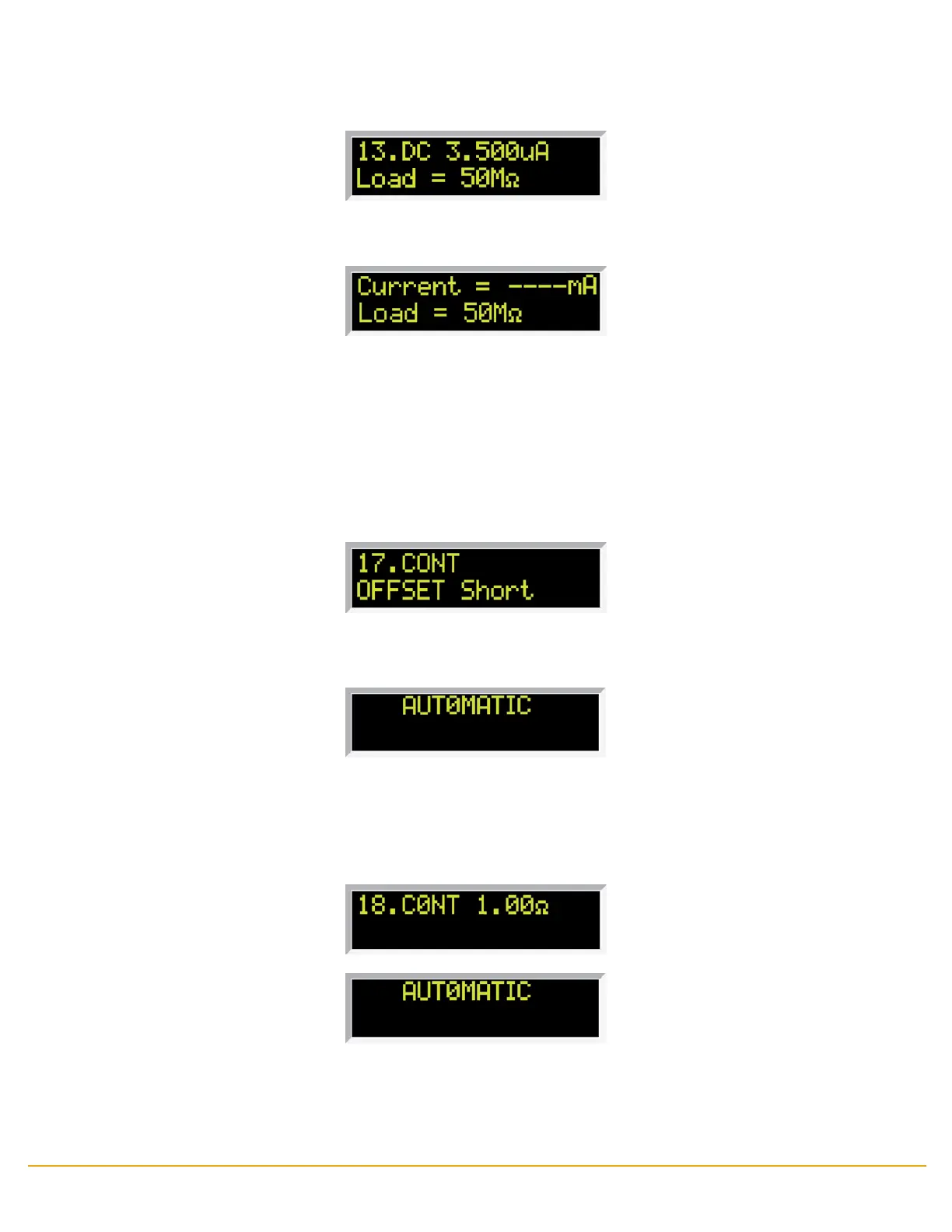
6. To calibrate Continuity Oset
Please short the RETURN and CONT. CHECK connectors.
Rotate the yellow knob until the display shows:
Then press the TEST button on the front panel. The tester will execute automatic calibration process. The process does not
require data entry. The tester will provide around 300VDC on the output connectors and the display will show:
7. To calibrate Continuity 1Ω
Please short the RETURN and CONT. CHECK connectors with a 1Ω resistor.
Rotate the yellow knob until the display shows:
8. Exit Calibration Mode
When all calibration parameters are completed successfully POWER cycle the tester to exit from the calibration mode and to
return to the test mode.
Then the display will show a value similar to that of the standard.
Turn and press the rotary knob to enter the reading of the standard AC Ammeter into the tester. Once all digits are entered
the tester will advance to the next calibration point.
 Loading...