EasyManua.ls Logo

IKUSI TM70 Series - User Manual

IKUSI TM70 Series
213 pages
Go to English
Print Icon
To Next Page IconTo Next Page
Loading...
TM70Be V4.1 (03/12) 1121174.pdf
IKUSI se reserva el derecho de modificar esta información sin previo aviso.
MANUAL DE INSTALACIÓN Y DE
UTILIZACIÓN
TM70
TRANSMISOR BOTONERA
MODELOS T70/1 & T70/2 (DOS PASOS)
MODELOS T70/1 & T70/2 (PROPORCIONAL)

Table of Contents

Question and Answer IconNeed help?

Do you have a question about the IKUSI TM70 Series and is the answer not in the manual?

Summary

Declaration of Conformity 870 MHz ISM Band

Declaration of Conformity 433 MHz ISM Band

Safety Instructions

What You Must Do

Essential procedures and actions required for safe and proper equipment use.

What You Must Not Do

Prohibited actions and conditions to avoid for safe and proper equipment use.

Installation

The CB70 (BC70 K) Battery Charger

Details on installing and using the CB70/BC70K battery charger.

Receiver Installation

Procedure for finding a suitable location and installing the receiver unit.

Starting Up

Step-by-step guide for powering on and initializing the system.

Using the Set

Maintenance

Troubleshooting

Guidance on identifying and resolving common operational issues using LED indicators.

Frequency Change

Base Channel Frequency Change

Detailed steps for entering programming mode and changing the base channel frequency.

First Come - First Served Operation

LA70 & LA70 M Range Limiter Option

System Description

How the range limitation option determines transmitter location and deactivates controls.

Infrared Sensor

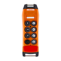
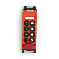
Functionality and location of the infrared sensor in the remote control transmitter.

LA70 Infrared Transmitter

Description of the LA70 infrared transmitter and its emission angles.

LA70 Installation

Instructions for installing the LA70 infrared transmitter, including power and connections.

LA70 M Infrared Transmitter

Details of the LA70M range limiter, a modular and compact redesign.

LA70 Installation and Connections

Installation and connection procedures for the LA70M infrared transmitter and its modules.

Pitch & Catch Operation

Tandem Operation

Analogue Feedback; In 0-10 v Option; Calibration

Calibration of the Analogue Feedback with LCD Display

Step-by-step guide to calibrate analogue input using the LCD display on transmitters.

T70;1 & T70;2 ATEX Transmitters

Binary Rotary Switch Option

T70;1 & T70;2 with Proportional Control

IKUSI TM70 Series Specifications

General IconGeneral
BrandIKUSI
ModelTM70 Series
CategoryTransmitter
LanguageEnglish

Related product manuals