8
Rev.13052022
INSTALLATION PREPARATION
DOOR HINGE
The ILREF256I/2 is available with left or right hand hinge options, however, each model is still reversible
The ILREF316/2 model are supplied in right hand hinge only but is reversible
The ILFRZ model are supplied in left hand hinge only but is reversible
To change the door hinge side, please follow the instructions on page 12
This appliance/s are designed to t into cabinetry with 18mm thickness
This appliance must never be installed close to its sources or cooking appliances. It should also not been stored in damp
locations. Seek the help of another individual, when installing this appliance. Is appliances may have sharp edges. You should
wear adequate protection equipment for the task and installation environment.
To ensure the appliance is level, you should use the height adjustable feet at the front of the appliance
The cooling system at the rear of the appliance must not touch the rear wall
The appliance must be installed with adequate ventilation. Insure that there is a clear rinse above the appliance to allow air to
escape and that there is space between the rear of the appliance and the wall
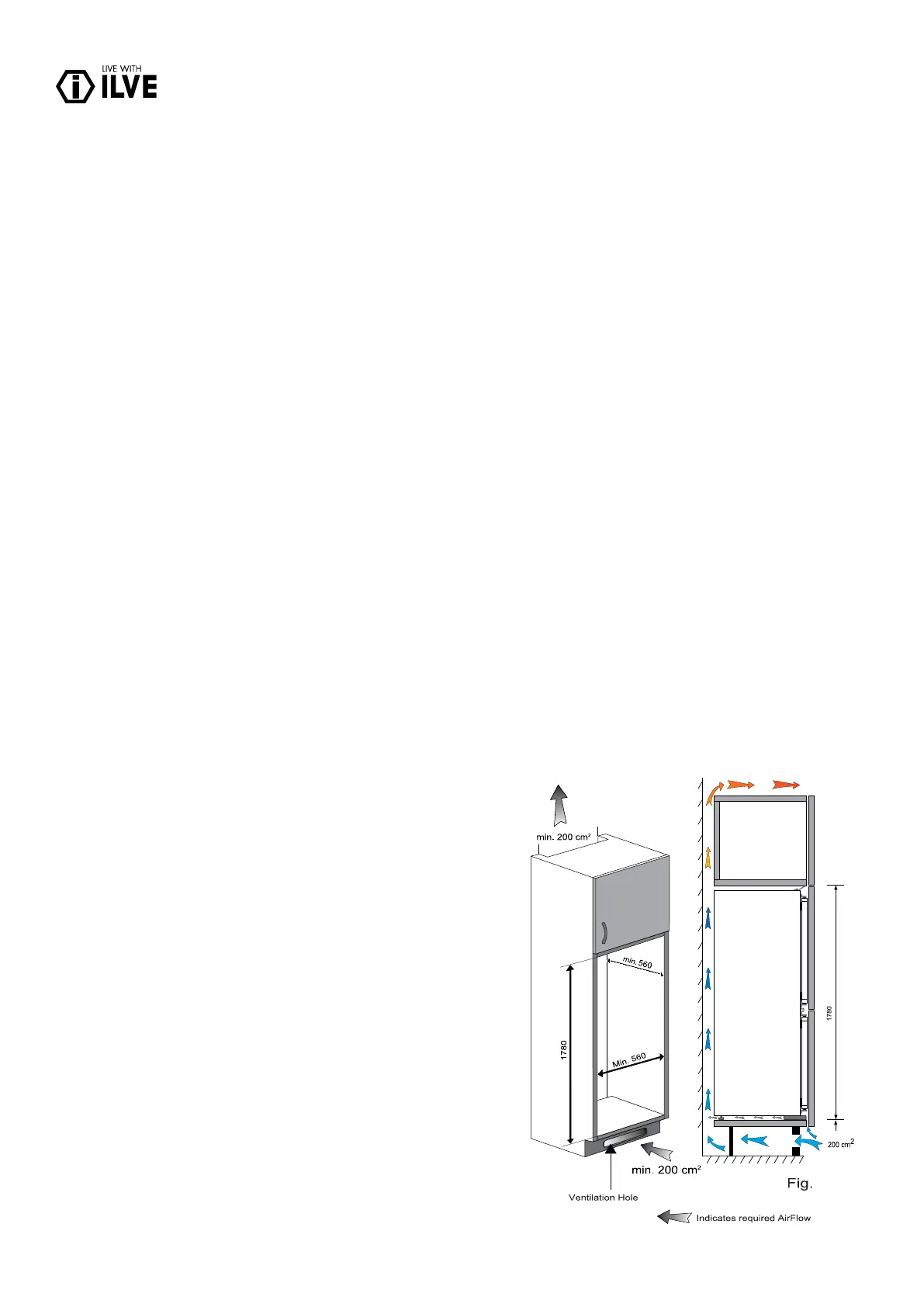
VENTILATION
The main consideration when installing this refrigerator unit into a tted kitchen is ventilation. The heat removed from the cooling
compartment needs to evaporate into the atmosphere. Incorrect ventilation can lead to premature compressor failure, excessive
power consumption, total system failure and may void the warranty provided with your appliance. What products intended to be
installed into a tall housing unit, the following requirements need to be met.
• minimum inlet vent area 200 cm2
• minimum outlet vent area 200 cm2
The open channel at the rear is clearly shown. For the correct operation of the appliance it is important that at the top of the
housing unit it is not blocked off. Channel depth of 50 mm is normal with most units. If ventilation hole is required in the plinth of
the unit, this allows air to be drawn over the compressor and heat exchange. Required airow can be achieved by removal of a
thin section of the plinth (recommended 600mm x 10mm minimum)
ILFRZ217/2
Recommended size of vent opening for the column freezer is:
500 x 30mm. If the furniture does not allow free air into the room
then a plinth vent, or other means of ventilation needs to be provided
to ensure a natural ow of air There should be space at the rear
of the cabinet to allow cool air to be drawn over the condenser.
Recommended: 500 x 35mm (recommended 600mm x 10mm).
* Please note a plinth vent / grill is not included with the appliance.
This is given as a guide to aid installation. Your installer will be able
to determine if you would be required to buy a plinth vent / grill for
your type of plan view of rear ventilation gap installation or not.
Fig. 1
The open channel at the rear is clearly shown. For the correct
operation of the appliance it is important that the top of the housing
unit is not blocked off. A channel depth of 40-50mm is normal with
most units. A ventilation hole is required in the plinth of the unit; this
allows air to 15 be drawn over the compressor & heat exchange.
The required air ow can be achieved by removal of a thin section
of plinth (recommended 600mm x 10mm minimum).
As a rule, there that can get in and out, the better and more efcient
the operation of your product will be.
1