INSTALLATION PROCEDURES
3-19
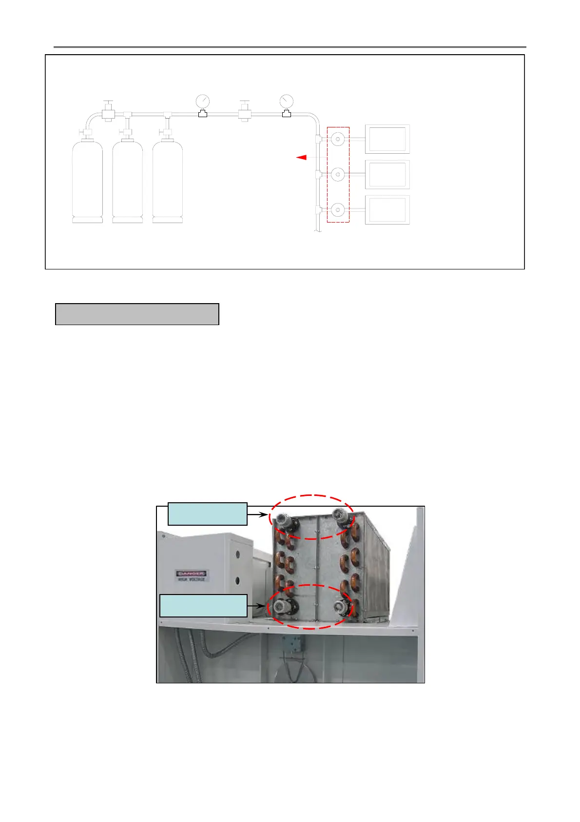
Figure.3-16 Typical of Gas Installation
Piping must be installed in accordance with good commercial steam system practice. Care
must be exercised when leveling steam dryers in final position. After leveling the dryer, check the
downward pitch of the heat exchanger from front to rear with a level. Likewise, check the
downward pitch of the return condensate manifold toward its outlet part. Absence of these
downward pitches will result in probable water hammer and premature heat exchanger fracture and
leakage.
The presence of condensate in the steam will cause water hammer and subsequent heat
exchanger failure. The steam supply connection must be taken from the top of a well-dripped steam
main. If the supply run – out to the dryer exceeds 20 feet, it should be dripped just before the
control valve with a proper trap and dirt pocket.
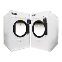
Figure.3-17 Typical of Steam Installation
H. STEAM INFORMATION
MAIN GAS SUPPLY TANKS
HIGH PRESSURE 0-300PSI
PRESSURE
RELIEF VALVE
HIGH PRESSURE
GAUGE 0-300PSI
PRESSURE GAUGE 0-60PSI
MEASURING 7PSI (0.48BAR)
HIGH PRESSURE
REGULATOR
GAS SUPPLY LINE 7PSI
LOW PRESSURE
SECOND STAGE
GAS REGULATOR
MAX INLET PRESSURE
10PSI (0.69BAR)
OUTLET PRESSURE
12-14 INCHES WC. (LPG)
4.5-14 INCHES WC. (NG)
GAS DRYER MACHINE
WITH GAS VALVE MAX INLET
PRESSURE 0.5PSI BUT IF USE
SECOND STAGE REGULATOR
WITH 11 INCHER WC. 0.41PSI (LPG)
4 INCHES WC.0.145 PSI (NG)
Steam Inlet
Steam Return