IMER U.S.A. Inc.
COMBI 250 VA
2
Dear Customer,
Congratulations on your choice of purchase: IMER saws are the result
of years of experience and are equipped with all the latest technical
innovations.
- WORKING IN SAFETY
To work in complete safety, read the following instructions care-
fully.
To work in complete safety, read the following instructions carefully be-
fore using the machine.
To work in complete safety, read the following instructions carefully be-
fore using the machine.
This OPERATION AND MAINTENANCE manual must be kept on site
by the person in charge, e.g. the SITE FOREMAN, and must always be
available for consultation.
The manual is to be considered integral part of the machine and must
be kept for future reference (EN 12100-2) until the machine is disposed
of. If the manual is damaged or lost, a replacement may be requested
from the manufacturer.
The manual contains important information regarding site preparation,
machine use, maintenance procedures, and requests for spare parts.
Nevertheless, the installer and the operator must both have adequate
experience and knowledge of the machine prior to use.
To guarantee complete safety of the operator, safe operation and long
life of equipment, follow the instructions in this manual carefully, and
observe all safety standards currently in force for the prevention of ac-
cidents at work (use of safety footwear and suitable clothing, helmets,
gloves, goggles etc.).
- Make sure that all signs are legible.
- It is strictly forbidden to carry out any form of modifi cation to
the steel structure or working parts of the machine.
IMER INTERNATIONAL declines all responsibility for failure to com-
ply with laws and standards governing the use of this equipment, in
particular; improper use, defective power supply, lack of maintenance,
unauthorised modifi cations, and partial or total failure to observe the
instructions contained in this manual.
IMER INTERNATIONAL reserves the right to modify features of the saw
and contents of this manual, without the obligation to update previous
machines and/or manuals.
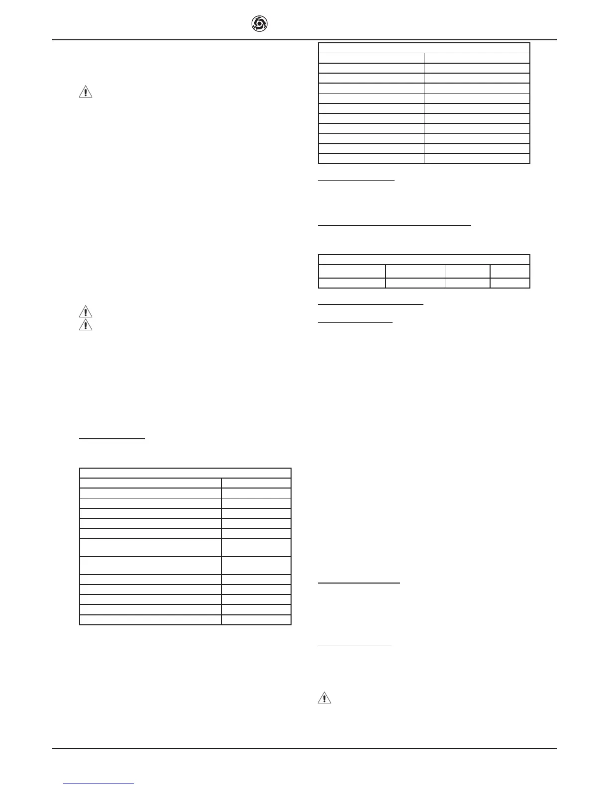
1. TECHNICAL DATA
Technical data are stated in table 1 and electrical specifi cations in table
2.
Table 1 - TECHNICAL DATA
Model Combi 250 VA
Max. blade diameter 10 inches
Diamond Blade hole diameter 5/8 inches
Single phase 115V/60Hz motor power 1.3 kW
Max. blade rotation speed 3.400 rpm
Cutting table dimensions 850x500 mm
Length of 90° cuts (thickness= 10mm)
Length of cuts from above
550 mm
600 mm
Maximum cut depth with single stroke
Maximum cut depth with two stroke
66 mm
105 mm
Water pump fl ow rate 13 L/1’
Water tank capacity 36 L
Machine dimensions 1050x565x480 mm
Packed machine dimensions 1090x610x525 mm
Weight with packaging 45.5 Kg
Table 2
Feature Motor (115V/60Hz)
Power (kW) 1.3
Rated voltage (V) 115
Frequency (Hz) 60
Absorbed current (A) 14.4
Number of poles 2
rpm 3400
Service type S6 40%
Insulation category F
Protection category IP55
Capacitor (μF) 110 (Ø 50x120)
2. DESIGN STANDARDS
Combi 250 VA saws have been designed and manufactured according
to the following standards: UNI EN 12418:2001; EN 12100-1/2:2005;
EN 60204-1:2006.
3. SOUND PRESSURE LEVEL AND VIBRATIONS
Table 3 shows the sound pressure level measured loadless at the ope-
rator’s ear (L
pA
) and of the vibrations transmitted during operation.
Table 3
Model Type of motor L
pA
A
eq
Combi 250 VA Electric 86 dB 2.57 m/s
2
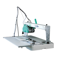
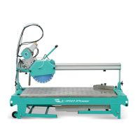
4. GENERAL SAW DESCRIPTION
4.1 General description
The Combi 250 VA is a saw comprising the following main sub-groups:
• cutter head (ref.A, fi g.1)
• runner guide and arms (ref.B, fi g.1)
• cutting tables and heads (ref.C, fi g.1)
• water collection tank (ref.D, fi g.1)
• frame (ref.E, fi g.1)
The cutting head is mounted on a reinforced aluminium profi le and is
equipped with horizontal and vertical movement facilities. The alumi-
nium profi le is hinged onto die-cast arms (ref.F, fi g.1) and the entire
unit can rotate through 45° (fi g.2) by means of the relative handwheels
(ref.G, fi g.2).
The machine is supported by a special metallic frame. There is a
shockproof plastic tank between the machine and the frame. The water
immersion pump is mounted below the cutting surfaces on a special bra-
cket and supplies a water distributor inside the blade guard for cooling
the cutting blade during operation.
The high resistance plastic handle (ref.H, fi g.2), is equipped with the
main ON-OFF switch on the operator side to facilitate saw activation
and shutdown.The raised position of the red OFF button on the handle is
designed to facilitate shutdown of the machine in the event of an emer-
gency. The motor capacitor is located in a protected position inside the
handle.
The saw is fi tted with a guard to guarantee optimal safety during opera-
tion and to protect the user during cutting cycles.
A valve is mounted above the blade guard to adjust the fl ow rate of water
delivered to the cutting blade.
4.2 Processable materials
This saw has been designed for cutting the following materials: ceramic
tiles, masonry and stone in general with maximum dimensions com-
patible with the length, cutting depth and dimensions of the surfaces
specifi ed in table 1.
Maximum weight of processable materials: 25 kg.
4.3 Unsuitable material
Materials unsuitable for this machine are all those not specifi ed in pa-
ragraph 4.2.
In any event, before using the saw with materials other than as specifi ed
by the manufacturer for this saw model, contact IMER INTERNATIONAL
S.p.A.
- Use of this machine with workpieces outside the specifi ed
dimensions is strictly prohibited and constitutes a hazard for the
operator.
 Loading...