1
2
3
5
4
43
42
35
INSTALLERUSERMAINTENANCE TECHNICIAN
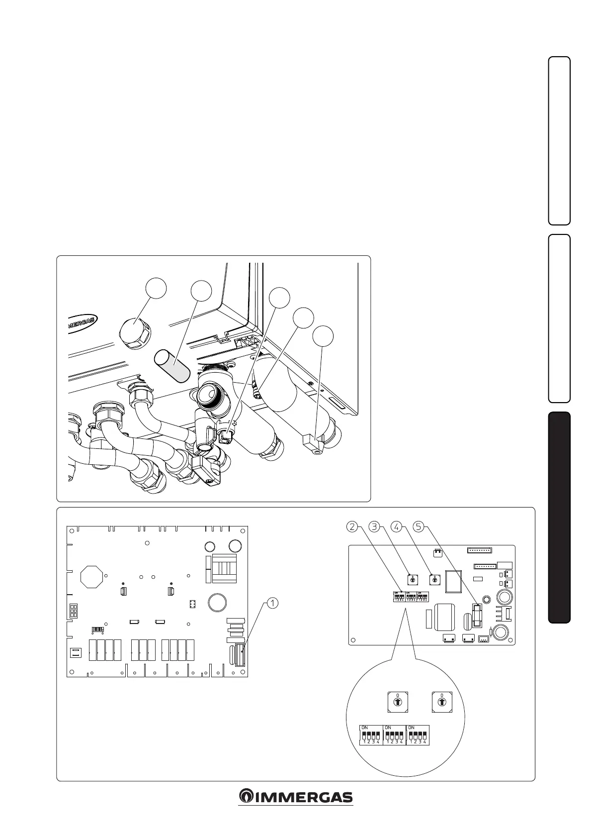
3.3 SYSTEM FILTER.
e indoor unit has a lter on the system return
fitting to keep the system in good operating
conditions.
Periodically and when necessary, the lter can be
cleaned as described below (Fig. 42).
Close the tap (4) and the tap (3) with a 12mm
spanner, drain the water contents in the indoor
unit using the draining valve (4).
Open the cap (1) and clean the lter (2).
3.4 TROUBLESHOOTING.
N.B.: maintenance interventions must be carried
out by an authorised company (e.g. Aer-Sales
Technical Assistance Service).
- Smell of gas. Caused by leakage from gas circuit
pipelines. Check sealing eciency of gas intake
circuit.
- Repeated ignition blocks. No gas, check the
presence of pressure in the network and that
the gas adduction cock is open. Incorrect
adjustment of the gas cock, check the correct
calibration of the gas valve.
- Irregular combustion or noisiness. It may be
caused by: a dirty burner, incorrect combustion
parameters, intake-exhaust terminal not cor-
rectly installed. Clean the above components
and ensure correct installation of the terminal,
P.C.B. Communication P.C.B.
Key:
1 - T 3.5 A fuse
2 - Switch SW 05 - 07
3 - Switch SW 02
4 - Switch SW 04
5 - T 5.0 A fuse
PLEASE NOTE: Switch 2 must be set to ON, while
Switches 3 and 4 must be set to 0.
check correct setting of the gas valve (O-Set
setting) and correct percentage of CO
2
in ue
gas.
- Frequent activation of the temperature over-
load thermostat. It can depend on the lack
of water in the heat generator, little water
circulation in the system or blocked pump.
Check on the pressure gauge that the system
pressure is within established limits. Check
that the radiator valves are not closed and also
the functionality of the pump.
- Siphon blocked. is may be caused by dirt or
combustion products deposited inside. Check,
by means of the condensate drain cap, that
there are no residues of material blocking the
ow of condensate.
- Heat exchanger blocked. is may be caused
by the drain trap being blocked. Check, by
means of the condensate drain cap, that there
are no residues of material blocking the ow of
condensate.
- Noise due to air in the system. Check opening
of the special air vent valve cap (Part. 31 Fig.
30). Make sure the system pressure and expan-
sion vessel pre-charge values are within the set
limits; e factory-set pressure values of the
expansion vessel must be 1.0 bar, the value of
system pressure must be between 1 and 1.2 bar.
Check that system lling and air bleeding has
been performed according to the requirements.
- Noise due to air inside the condensation
module. Use the manual air vent valve (Part.
17 Fig. 30) to eliminate any air present in the
condensation module. When the operation has
been performed, close the manual vent valve.