Analog signals (SET1, SET2, SET3)
When used as output. 5 mA max. Load allowed per
output.
0.5 mA load is added for most configurations.
Output current sink
range
Current sink to COM if configured as output.
- 230 VAC, 3 A, AC1
-
32 VDC, 3 A
Potential free changeover contact.
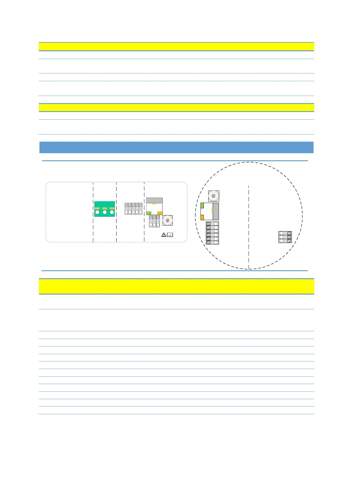
3. MODULE LAYOUT
2
1
3
4
5
6
7
8
9
0
NC
C
NO
RELAY ANALOG
A/D+
SET2
SET3
SET1
+24 V
0V
B/D-
0V
RS 485
ETHERNET
LED2 LED1
MODE
2
1
3
4
5
6
7
8
9
0
SET3/ FB
SET2 / MAX
COM / 0V
SET1 / RUN
A/D +
B/D -
NC
C
NO
LED2 / ACT
LED1 / LINK
ETHERNET
MODE
Description
Mode selection rotary switch. Used to configure mode of operation for the circuit. See section
4.3 “Module mode selection”.
Slowly blinking when module is powered.
Blinking fast when Modbus Error
Permanently lid when Ethernet link established.
10BASE-T RJ-45 connector.
Indicates Ethernet activity or Modbus activity.
RS-485 negative data signal for Modbus.
RS-485 positive data signal for Modbus.
RS-485 common and analog input common (ground).
Normally closed relay contact. Opens when relay is active.
Normally open relay contact. Closes when relay is active.