12
4.1. Assembly
A front panel cut-out of 45
+0.6
x 92
+0.8
mm is necessary to install the DA 6000-N. The required installation
depth is ≥ 165 mm. The screw clips provided with the DA 6000-N are for fastening it after it has been in-
serted into the opening.
The electrical connections should be made as shown in the schematic below.
4.2. Electrical connections on the rear panel
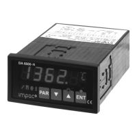
4.2.1. Power supply connection
The DA 6000-N can be powered by a mains
voltage of 85 to 265 V AC (connections 1, 2 and
3) or, alternatively with a voltage of 18 to 30 V
DC (connections 4 and 5).
Please be sure that the mains cable connec-
tions are sufficiently protected from contact!
L
85...265V~
N
PE
3
2
1
-
+
5
4
6
8
9
10
7
18...30V=
Power Input
Note:
Only one of the two power supply possibilities can be connected!
The mains supply connection must meet the requirements of DIN/VDE regulation 57 411!
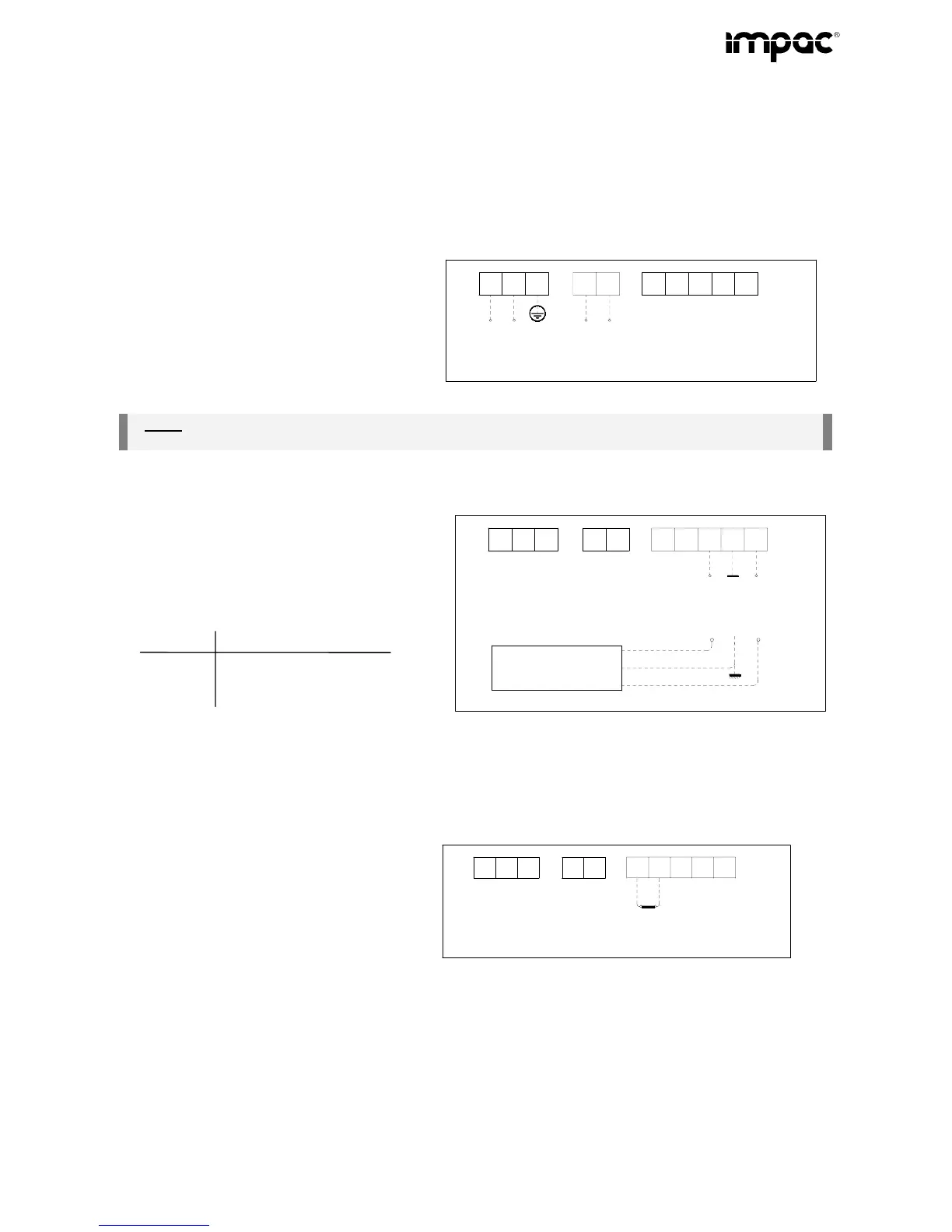
4.2.2. Interface connection
The digital interface is for the connection to a
digital. The serial interface is galvanically iso-
lated from other units connected to the display
and can be ordered as either an RS232 or
RS485. This contact arrangement is as fol-
lows:
Contact RS232 RS485
8 Rx A
9 Gnd S
10 Tx B
3
2
1
5
4
6
8
9
10
7
Rx
Gnd
Tx
(RS232)
A
B
S
(RS485)
Digital -
pyrometer
violett
Gnd
RxD
TxD
rot
schwarz
(Both RS232 and RS485 can just be use for one Pyrometer)
4.2.3. Connecting the control input (switching bridge)
Partial keyboard lock
Parameters can only be set using the operating
buttons, when the connection between 6 and 7
is open (the LED above the enter button will be
illuminated)
3
2
1
5
4
6
8
9
10
7
Disable
Enter