1. Connect each of the component video outputs from your devices (DVD player, HD
cable/satellite receiver, video game player, etc.) to a set of Inputs (1-5) Y, Pb and Pr jacks
on the back of the switch or Input (6) Y, Pb, and Pr jacks on the front of switch.
2. Connect your device’s optical outputs to a set of Optical Input (1-5) jacks on the back of
the switch or Input 6 Optical jack on the front of the switch. If devices do not have an
optical output, connect its stereo L/R audio outputs to a set of stereo L/R audio Inputs (1-
5) jacks on the back of the switch. Front panel Input 6 features 3.5mm jack for stereo L/R
connections. A 3.5mm to RCA “Y” adapter (not included) must be used for this
connection.
Note: This device does not convert TOSLINK to analog audio or analog audio to
TOSLINK. Audio switching follows video.
3. Connect component video Outputs (1-2) Y, Pb and Pr of the matrix switch to the
component video inputs of two TVs/monitors.
4. Using a TOSLINK cable, connect the ends from the optical Outputs (1-2) on the switch to
the optical inputs on two A/V receivers (or digital audio recorders). If devices do not have
optical inputs, use RCA audio cables to connect from the matrix switch’s L/R audio Output
(1-2) to RCA L/R audio inputs on two A/V receivers (or audio recorders).
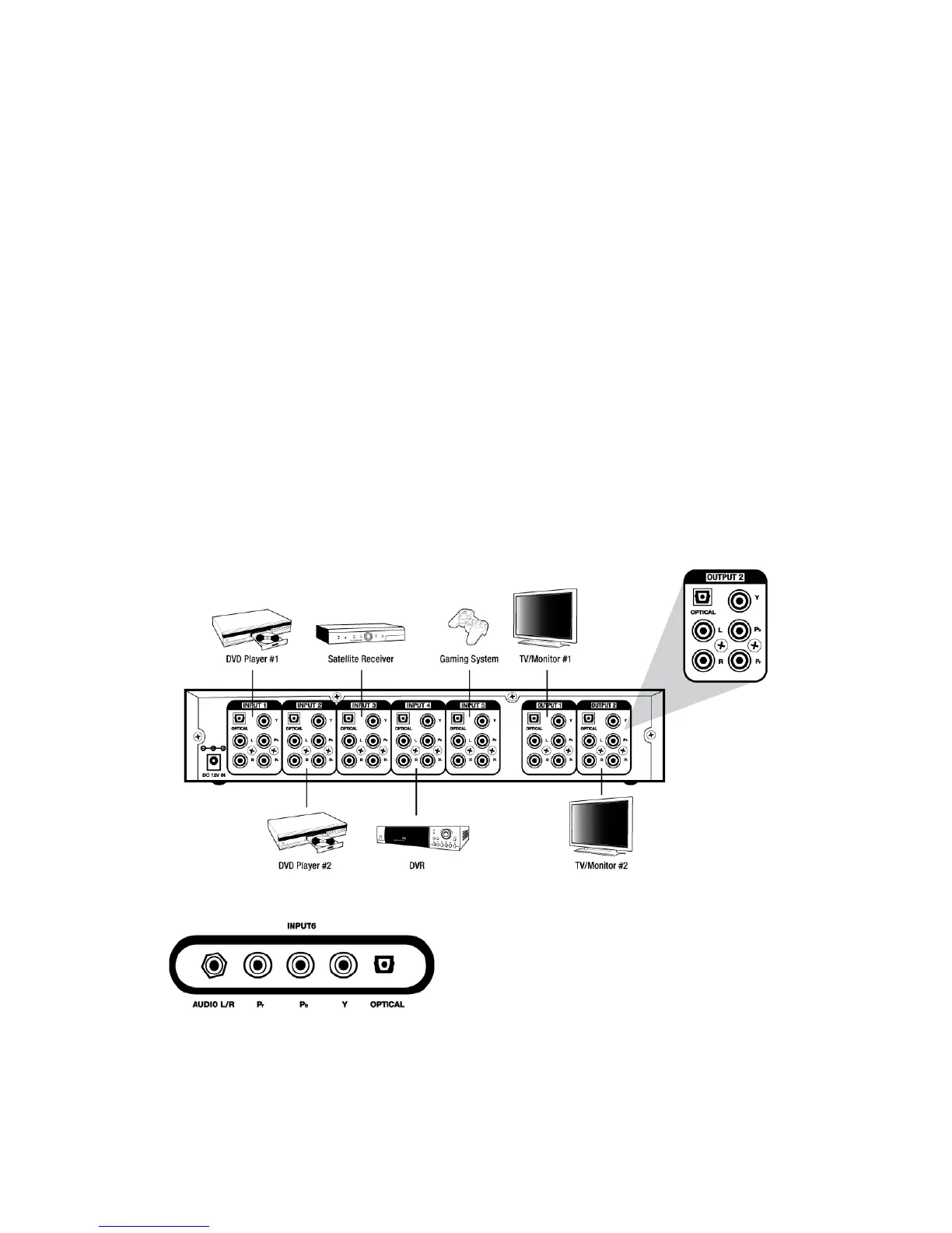
Example diagram:
Rear Panel
Front Input
3