Sept, 2019 IMPCO Technologies PPI-68 REV. E
3030 South Susan St. Page 14 of 15
Santa Ana, CA 92704
www.impcotechnologies.com
3030 S Susan Street, Santa Ana, CA 92704
Ph: +1 714 656 1200 Fax: +1 714 656 1400
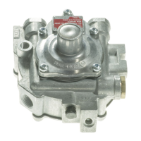
21. Place the secondary diaphragm (23) on the
regulator body (2) so the straight edge of
diaphragm is at the top (12 o’clock position).
Placing your finger between the vacuum lock
diaphragm (15) and the secondary lever (23),
depress the diaphragm, lift the lever then slide the
lever rod through the center pin of the diaphragm.
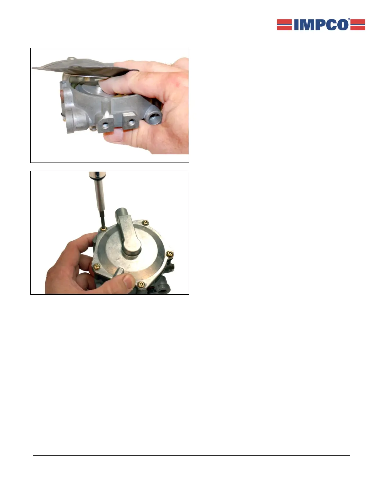
22. Place the secondary diaphragm (17) so the
straight edge is at the top of the regulator, then
place the cover (18) on the regulator body and
align the screw holes. Carefully start all five
screws (13) and washers (34)(Series I only)
through the cover and diaphragm holes, then
tighten evenly to 30 in. lbs. ± 5 in. lbs. (3.29 N•m ±
0.57 N•m).
23. Install the regulator.
NOTE: The atmospheric vent (small opening on the edge of the back cover) must be at the lower 45°
position when mounted.
24. Leak check all fittings, covers and fuel connections using an electric leak detector or a commercial
leak detector solution:
a. Run the engine until it is at full operating temperature.
b. Reset idle mixture carbon monoxide (CO) percent to factory specifications.
c. Replace idle mixture tamper-resistant cap (32).
 Loading...