Do you have a question about the Impex Iron Grip Strength IGS-4350 and is the answer not in the manual?
Key safety measures to follow when operating the exercise machine.
Instructions for maintaining the machine for optimal performance and longevity.
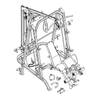
Connect the two base frames with a cross brace using specified bolts and washers.
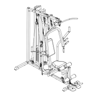
Detailed instructions for attaching vertical frames, guide rods, and safety stop frames.
Attach rear vertical beam, weight glide base, and backrest board using specified hardware.
Attach weight glide post, sliding weight post, and upper frame using specified components.
Attach butterfly base, pulley bracket, and arm pad to rear vertical frame.
Attach upper cable, pulleys, and lat bar, and connect sleeves and clips.
Attach butterfly cable to pulleys, brackets, and left butterfly.
Attach lower cable, pulleys, foot plate, and various exercise accessories.
Install lifting sleeve, weight bar, weight posts, sleeves, and bar holders.
Attach main frame to stabilizers and incline adjustment bar.
Attach bushings, backrest supports, and seat support frames to the main frame.
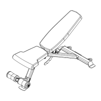
Secure backrest board and seat pad to the backrest and seat support frames.
Attach leg developer, insert foam tubes and rolls, and add Olympic sleeve.
Attach arm curl pad, stand, and support frame to the leg developer.
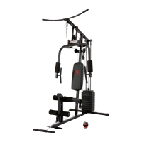
| Product Name | Iron Grip Strength IGS-4350 |
|---|---|
| Brand | Impex |
| Category | Home Gym |
| Weight Capacity | 300 lbs |
| Material | Steel |
| Color | Black |
| Features | Adjustable resistance |