EasyManua.ls Logo

Impex IRON GRIP STRENGTH TSA-9900 User Manual

Impex IRON GRIP STRENGTH TSA-9900
33 pages
To Next Page IconTo Next Page
Page #1 background imageLoading...
Page #1 background image
IRON GRIP STRENGTH
Corner Gym
TSA-9900
IMPEX INC.
14777 DON JULIAN RD., CITY OF INDUSTRY, CA 91746
Tel: (800) 999-8899 Fax: (626) 961-9966
www.impex-fitness.com
info@impex-fitness.com
NOTE:
Please read all instructions
carefully before using this
product
Table of Contents
Safety Notice
Hardware Pack
Assembly Instruction
Parts List
Resistance Chart
Warranty
Ordering Parts
Model
TSA-9900
Retain This
Manual for
Reference
08-06-05
OWNER'S
MANUAL
Question and Answer IconNeed help?

Do you have a question about the Impex IRON GRIP STRENGTH TSA-9900 and is the answer not in the manual?

Impex IRON GRIP STRENGTH TSA-9900 Specifications

General IconGeneral
BrandImpex
ModelIRON GRIP STRENGTH TSA-9900
CategoryHome Gym
LanguageEnglish

Summary

IMPORTANT SAFETY NOTICE

PRECAUTIONS

General safety precautions for operating the exercise machine.

CARE AND MAINTENANCE

Guidelines for maintaining the exercise equipment.

WARNING LABEL REPLACEMENT

HARDWARE PACK

ASSEMBLY INSTRUCTIONS

STEP 1: Base Frame Assembly

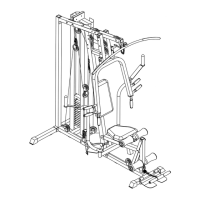
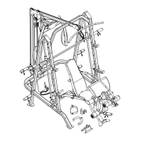
Instructions for assembling the base frame and guide rods.

STEP 2: Base Frame Connection

Attaching base frames and securing with bolts, washers, and nuts.

STEP 3: Weight Plates Installation

Installing weight plates and selector stem onto guide rods.

STEP 4: Vertical Frame Attachment

Attaching vertical frames to the base frames and securing them.

STEP 5: Frame Connections

Connecting upper frame, top socket assembly, and vertical frames.

STEP 6: Seat and Component Attachment

Attaching seat supports, leg developer, and butterfly components.

STEP 7: Leg Press Assembly

Attaching left seat support, leg press frame, and leg press plate.

STEP 8: Chin-up and Dip Station Setup

Attaching chin-up support, bar, dip supports, handles, and foot step.

STEP 9: Butterfly and Front Press Setup

Installing butterfly adjustment frames, front press base, and front press.

STEP 10: Vertical Press Setup

Attaching vertical press base and vertical press arms.

CABLE LOOP DIAGRAM

STEP 11: Upper Cable Routing

Attaching upper cable, pulleys, and securing them.

STEP 12: Butterfly Cable Routing

Connecting butterfly cables to pulleys and adjustment frames.

STEP 13: Lower Cable Routing

Attaching lower cable, pulleys, and checking cable tension.

STEP 14: Front Press Cable Routing

Routing front press cable through pulleys and securing it.

STEP 15: Vertical Press Cable Routing

Attaching short chain, vertical press cable, and pulleys for the selector rod.

STEP 16: Leg Press Cable Routing

Routing leg press cable through various pulleys and securing it.

FINAL ASSEMBLY STEPS

STEP 17: Seat and Handlebar Setup

Attaching seat pad, foam tubes, arm curl handle, lat bar.

STEP 18: Backrest and Pad Installation

Attaching backrest boards, seats, and arm pads, plus lubrication advice.

PARTS LIST

WEIGHT RESISTANCE CHART

LIMITED WARRANTY

ORDERING REPLACEMENT PARTS

How to order replacement parts by phone or website.

Related product manuals