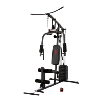
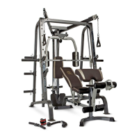
STEP 2 (See Diagram 2)
A.) Attach a Diagonal Support (#4) to the Lower Upright Beam (#5) and the Right Base Frame
(#2). Secure it to the Lower Upright Beam with two M10 x 3” Carriage Bolts (#17), Ø ¾”
Bent Washers (#18), and M10 Aircraft Nuts (#15). Secure it to the Right Base Frame with
two M10 x 2 ½” Carriage Bolts (#16), Ø ¾” Washers (#14), and M10 Aircraft Nuts (#15).
B.) Attach an Upper Upright Beam (#6) onto the right Lower Upright Beam (#5). Attach a Dip
Support (#9) to the Lower Upright Beam. Align the holes and secure them with two M10 x
3” Carriage Bolts (#17), Ø ¾” Bent Washers (#18), and M10 Aircraft Nuts (#15).
C.) Attach a Vertical Handle (#8) to the Dip Support. Secure it with one M10 x 1” Allen Bolt
(#27) and Ø 1” Bent Washer (#20).
D.) Repeat the above procedures A, B, & C to install the other side.
E.) Connect the two Upright Beams with a Cross Brace (#7) in the middle. Make sure the
“longer” side of the welded bracket faces downward. Secure each side with two M10 x 3”
Carriage Bolts (#17), ∅ ¾” Bent Washers (#18) and M10 Aircraft Nuts (#15). Do NOT
tighten all the Nuts and Bolts yet.
6