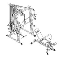
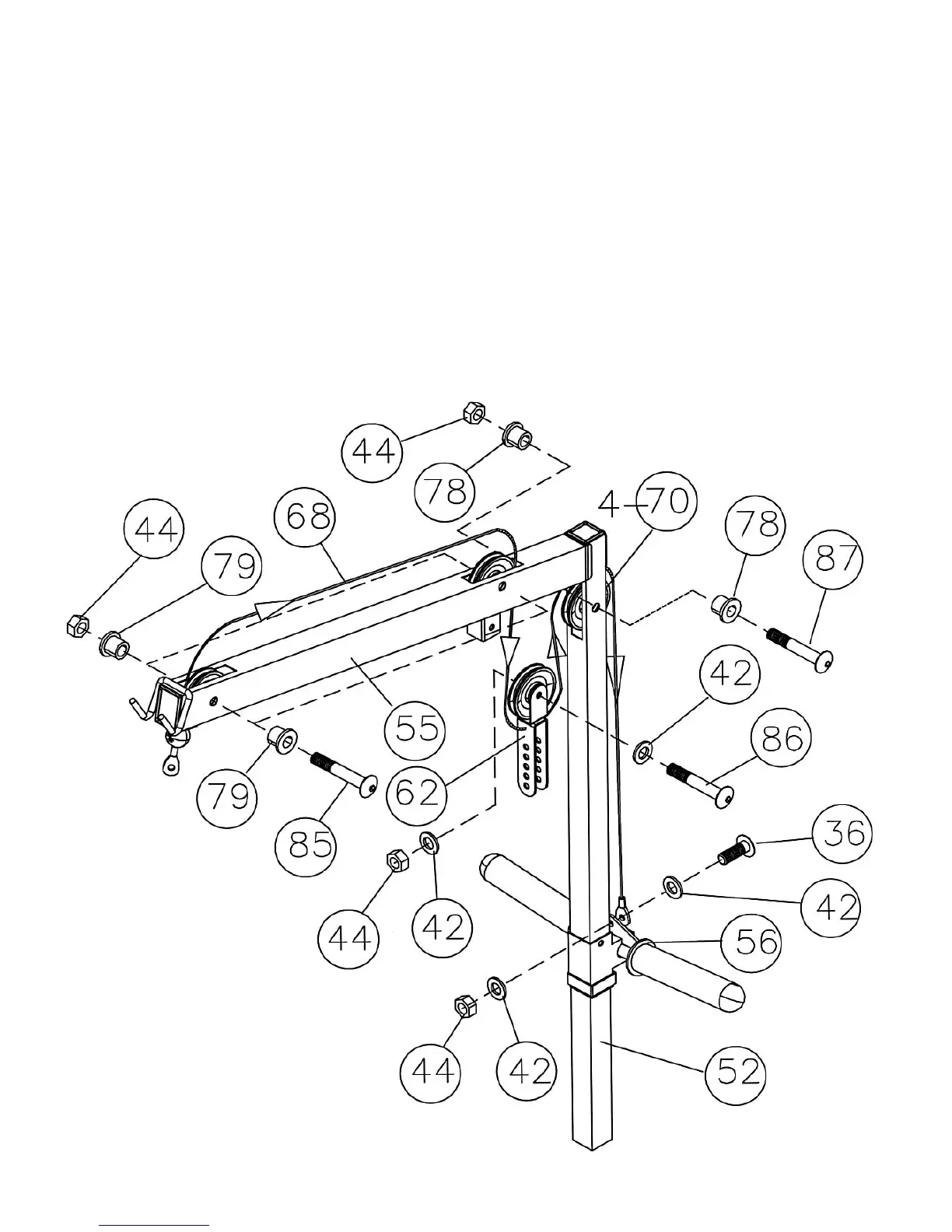
STEP 9 (See Diagram 9 & Cable Loop Diagram)
A.) Attach the 100” Upper Cable (#68) to the front opening on the Upper Frame (#55). Make
sure the ball stopper of the Cable is under the Frame.
B.) Attach a Pulley (#70) to the opening. Secure it with one M10 x 2 ½” Allen Bolt (#85), two 5/8”
Pulley Bushings (#79), and one M10 Aircraft Nut (#44).
C.) Draw the Cable along the Upper Frame towards the back of the machine to the opening on
the Upper Frame. Repeat Step B above to install a Pulley.
D.) Draw the Cable around the Pulley and downward. Attach a Pulley to the Double Floating
Pulley Bracket (#62). Secure it with one M10 x 1 ¾” Allen Bolt (#86), two ∅ ¾” Washers
(#42), and one M10 Aircraft Nut (#44). Let the Bracket hanging for now.
E.) Draw the Cable around the Pulley and up to the opening on the top of the Rear Vertical
Frame (#52). Attach a Pulley to the opening. Secure it with one M10 x 2 3/8” Allen Bolt (#87),
two ½” Pulley Bushings (#78), and one M10 Aircraft Nut (#44).
F.) Draw the Cable down to the Sliding Weight Post (#56). Secure the end of the Cable with
one M10 x ¾” Allen Bolt (#36), two ∅ ¾” Washers (#42) and one M10 Aircraft Nut (#44).
DIAGRAM 9
15