EasyManua.ls Logo

Impex Powerhouse Club PHC 710 User Manual

Impex Powerhouse Club PHC 710
10 pages
To Next Page IconTo Next Page
Page #1 background imageLoading...
Page #1 background image
NOTE:
Please read all instructions
carefully before using this
product
Safety Notice
Hardware Identifier
Assembly Instruction
Parts List
Warranty
Ordering Parts
Model
PHC 710
Retain This
Manual for
Reference
07-17-01
OWNER'S
MANUAL
POWERHOUSE CLUB
PHC 710
IMPEX FITNESS PRODUCTS
14777 DON JULIAN RD., CITY OF INDUSTRY, CA 91746
Tel: (800) 999-8899 Fax: (626) 961-9966
www.impex-fitness.com
info@impex-fitness.com
Question and Answer IconNeed help?

Do you have a question about the Impex Powerhouse Club PHC 710 and is the answer not in the manual?

Impex Powerhouse Club PHC 710 Specifications

General IconGeneral
BrandImpex
ModelPowerhouse Club PHC 710
CategoryHome Gym
LanguageEnglish

Summary

Before You Begin

Customer Support Information

Contact IMPEX for assistance: Toll-Free 1-800-999-8899, www.impex-fitness.com, info@impex-fitness.com.

Important Safety Notices

General Safety Precautions

Includes keeping children/pets away, single-person use, machine placement, moving parts awareness, and proper attire.

Health and Workout Recommendations

Stop workout if unwell, consult physician, warm-up, and use of a spotter are recommended.

Pre-Exercise Medical Consultation

Consult physician before starting any exercise program, especially for individuals over 35 or with health conditions.

Hardware Identifier

Hardware Size Identification

Visual guide to identify hardware sizes in millimeters (M6, M8, M10) and inches (1/2”, 5/8”, 3/4”).

Hardware Component Diagrams

Illustrations of Hex Head Bolt, Carriage Bolt, Allen Bolt, Aircraft Nut, and Flat Washer for identification.

Replacement Parts Contact Information

Contact IMPEX at 1-800-999-8899 for assistance with defective or missing parts.

Assembly Instructions

Step 1: Assembling Main Frame Components

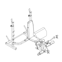
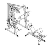
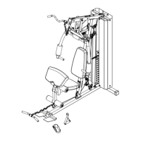
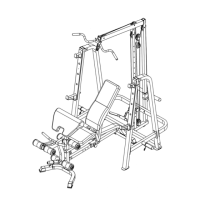
Connect upright beams, cross brace, and stabilizers using specified bolts, nuts, and brackets.

Step 2: Attaching Seat and Backrest

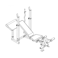
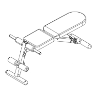
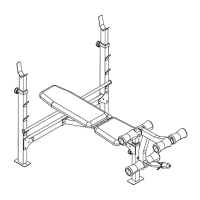
Attach seat bracket, seat pad, backrest supports, and backrest board using bolts, screws, and pins.

Step 3: Installing Leg Developer Assembly

Assemble and attach leg developer holder, leg developer, foam rolls, Olympic sleeve, and spring clip.

Exploded Diagram

Parts List

Limited Warranty

Ordering Replacement Parts

Process for ordering replacement parts, requiring model, part description, part number, and purchase date.

Related product manuals