Do you have a question about the Impex POWERHOUSE CLUB PWR 6 and is the answer not in the manual?
| Resistance | Weight Stack |
|---|---|
| Color | Black |
| Maximum User Weight | 300 lbs |
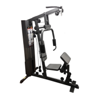
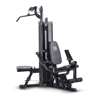
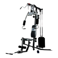
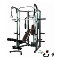
| Number of Stations | 6 |
| Exercises | Chest Press, Butterfly, Lat Pull Down, Leg Extension, Bicep Curl, Tricep Extension |
| Material | Steel frame |
| Included Accessories | Lat bar |
General safety precautions for operating exercise equipment, including user restrictions and proper usage guidelines.
Advice to consult a physician before starting any exercise program, especially for specific age groups or health conditions.
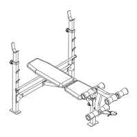
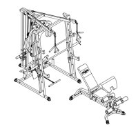
Attaching the main frame to stabilizers and incline adjustment bar using specified bolts and washers.
Attaching seat support frames, backrest supports, and sliding block to the main frame with various hardware.
Securing the backrest board and seat pad to the support frames using Allen bolts and washers.
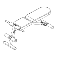
Attaching the leg developer, foam tubes, and Olympic sleeve, securing with axle and spring clip.
Attaching arm curl pad, stand, and curl bar support frame, and securing with pins.
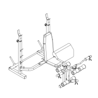
Attaching upright beams, supports, and stabilizers to the floor stabilizers and cross brace.
Connecting vertical frames, cross braces, weight posts, bar holders, and safety catches.
Sliding weight post and pulley bracket, attaching upper frame, and connecting chain to lat bar.
Attaching upper cable, pulleys, and securing cable ends to frames and weight post.
Attaching lower cable, pulleys, securing cables, and connecting shiver bar or handle.
Instructions and information required for ordering replacement parts for the product.