Motor Peak Current =
Rated Amps/Phase x 1.4
Maximum Motor Inductance
mH per Phase = 0.2 X Supply Voltage
Supply Voltage (+V)
Max. Inductance
(Per Phase)
+12 VDC
2.5 mH
+24 VDC
5 mH
+40 VDC
8 mH
+48 VDC
10 mH
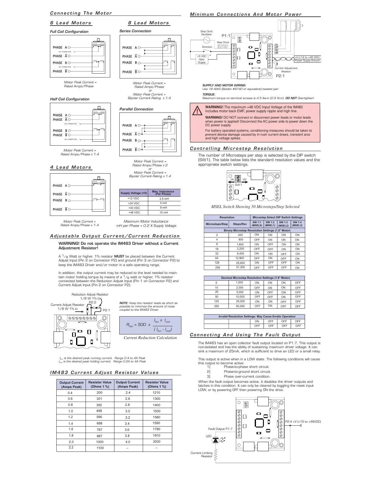
6 Lead Motors 8 Lead Motors
Full Coil Confi guration
Series Connection
Adjustable Output Current/Current Reduction
WARNING! Do not operate the IM483 Driver without a Current
Adjustment Resistor!
A
1
/
8
Watt or higher, 1% resistor MUST be placed between the Current
Adjust Input (Pin 2 on Connector P2) and ground (Pin 3 on Connector P2) to
keep the IM483 Driver and/or motor in a safe operating range.
In addition, the output current may be reduced to the level needed to main-
tain motor holding torque by means of a
1
/
8
watt or higher, 1% resistor
connected between the Reduction Adjust Input (Pin 1 on Connector P2) and
Current Adjust Input (Pin 2 on Connector P2).
Current Adjust Resistor
1/8 W 1% W
Reduction Adjust Resistor
1/8 W 1% W
P2:1
P2:2
NOTE: Keep the resistor leads as short as
possible to minimize the amount of noise
coupled to the IM483 Driver.
Current Reduction Calculation
I
Run
is the desired peak running current. Range 0.4 to 4A Peak
I
Hold
is the desired peak holding current. Range 0.2A to 4A Peak
IM483 Current Adjust Resistor Values
I
Run
x I
Hold
R
Red
= 500 x
( I
Run
- I
Hold
)
Output Current
(Amps Peak)
Resistor Value
(Ohms 1 %)
Output Current
(Amps Peak)
Resistor Value
(Ohms 1 %)
0.4
0.6
0.8
1.0
1.2
1.4
1.6
1.8
2.0
2.2
200
301
392
499
590
698
787
887
1000
1100
2.4
2.6
2.8
3.0
3.2
3.4
3.6
3.8
4.0
–
1210
1300
1400
1500
1580
1590
1780
1910
2000
–
Minimum Connections And Motor Power
+5 VDC
Opto
Supply
Step Clock
Oscillator
Direction
Current Adjustment
Resistor
ØA
ØA
ØB
ØB
Step Clock
P1:1
P2:1
Power Supply Ground
+V (+12 to +48 VDC)
+
SUPPLY AND MOTOR WIRING:
Use 18 AWG (Belden #9740 or equivalent) twisted pair.
TORQUE:
Maximum torque on terminal screws is 4.5 lbs-in (0.5 N-m). DO NOT Overtighten!
Controlling Microstep Resolution
The number of Microsteps per step is selected by the DIP switch
(SW1). The table below lists the standard resolution values and the
appropriate switch settings.
1
2
3
4
ON OFF
SW-1
MSEL Switch Showing 50 Microsteps/Step Selected
( (
Resolution Microstep Select DIP Switch Settings
Microsteps/Step
Steps/Rev
SW 1:1
(MSEL0)
SW 1:2
(MSEL1)
SW 1:3
(MSEL2)
SW 1:4
(MSEL3)
Binary Microstep Resolution Settings (1.8° Motor)
2
4
8
16
32
64
128
256
400
800
1,600
3,200
6,400
12,800
25,600
51,200
ON
ON ON ON
OFF ON
ON
ON
ON OFF ON ON
OFF
OFF
ON
ON
ON
ON
OFF
ON
OFF
ON
OFF ON
ON
OFF
OFF ON
OFF
OFF OFF
ON
Decimal Microstep Resolution Settings (1.8° Motor)
5
10
25
50
125
250
1,000
2,000
5,000
10,000
25,000
50,000
ON ON ON OFF
OFF ON
ON
OFF
ON OFF ON OFF
OFF
OFF
ON
OFF
ON ON
OFF
OFF
OFF
ON
OFF OFF
Invalid Resolution Settings: May Cause Erratic Operation
ON OFF OFF OFF
OFF OFF OFF OFF
Connecting And Using The Fault Output
The IM483 has an open collector fault output located on P1:7. This output is
non-isolated and has the ability of sustaining maximum driver voltage. It can
sink a maximum of 25mA, which is suffi cient to drive an LED or a small relay.
This output is active when in a LOW state. The following conditions will cause
this output to become active:
1] Phase-to-phase short circuit.
2] Phase-to-ground short circuit.
3] Phase over-current condition.
When the fault output becomes active, it disables the driver outputs and
latches in this condition. It can only be cleared by toggling the reset input
LOW, or by powering OFF then powering ON the drive.
Fault Output P1:7
LED
Current Limiting
Resistor
P2:4 +V (+12 to +48VDC)
WARNING! The maximum +48 VDC Input Voltage of the IM483
includes motor back EMF, power supply ripple and high line.
WARNING! DO NOT connect or disconnect power leads or motor leads
when power is applied! Disconnect the AC power side to power down the
DC power supply.
For battery operated systems, conditioning measures should be taken to
prevent device damage caused by in-rush current draws, transient arcs
and high voltage spikes.


 To Previous Page
 Loading...