INSTALLATION
1. After reading precaution, decide where you are going to install the unit. Also, see Fig.1.
2. Once the location has been determined, place the amplifier into position. Using a felt tip
pen or pencil mark the four holes to be drilled for mounting. NEVER use the amplifier as
a template for drilling. It is very easy to damage the amplifier surface in this manner.
3. Remove amplifier. Drill four 3.5 m/m holes into mounting surface. If you want to mount
4. If possible, test the system to ensure it is operating correctly before final mounting of
5.
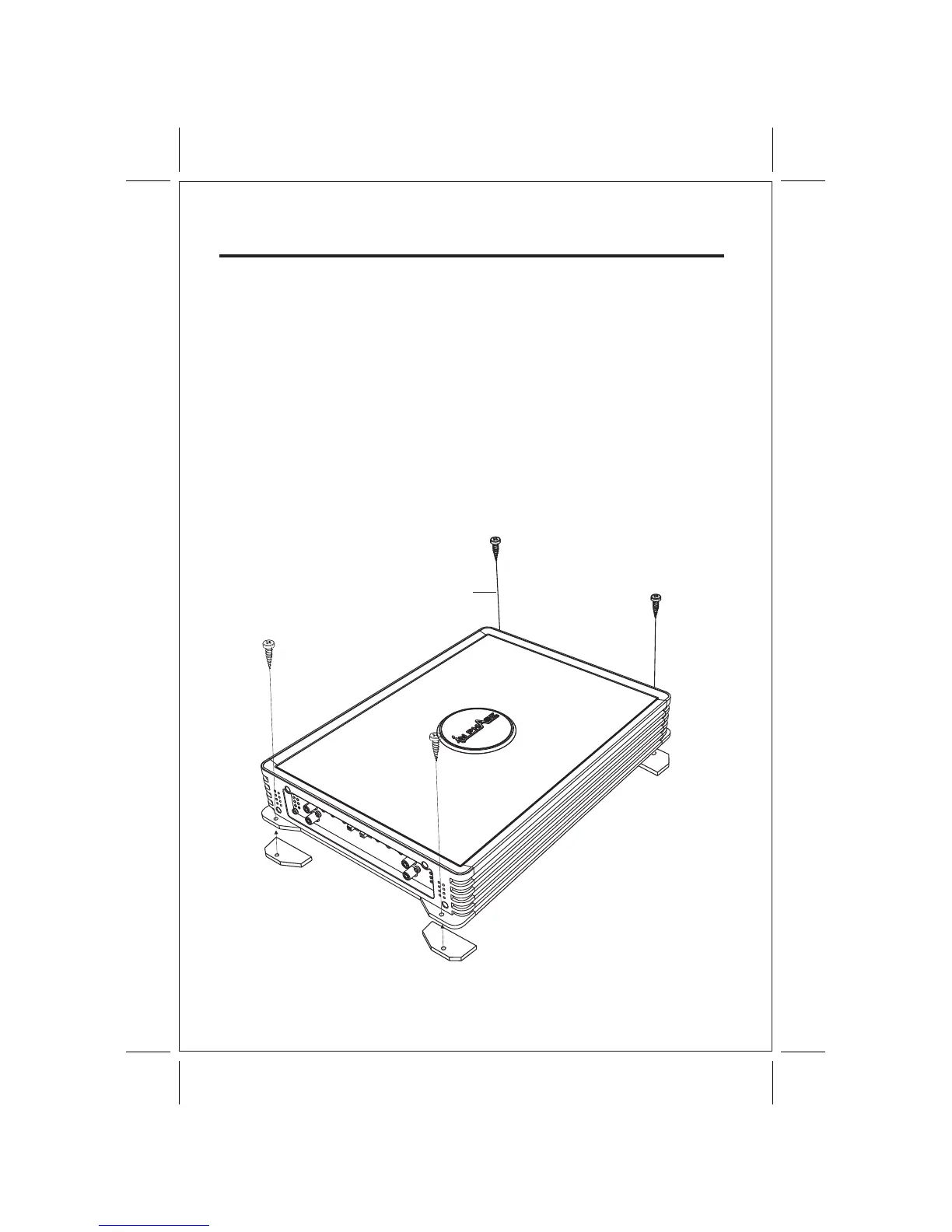
INSTALLATION DIAGRAM
MOUNTING:
Mount the amplifier using the supplied 4 self tapping screws.
the amplifier to MDF or wood panel, drill four 3.0m/m diameter holes into mounting surface.
the amplifier.
FIG.1
SELF TAP SCREWS
5