ZM622: INSTALLATION & OPERATION MANUAL
PAGE 5
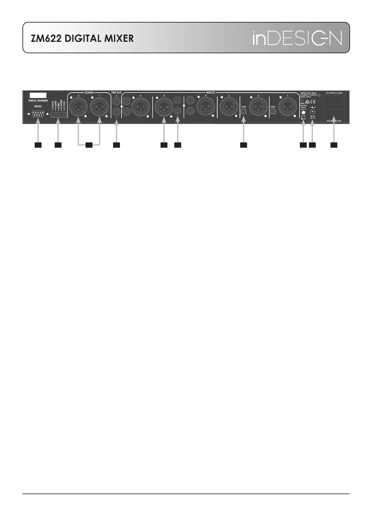
REAR PANEL
13. RS232: DB-9 connector for RS232 control. See page 6 for settings and a list of RS232 commands.
14. Tone generator connections: There are four alarm triggers: CHIME, ALERT, BELL and EVAC. These are
connected via the rear panel Phoenix connector. Each alarm is triggered by a (normally open) switch/
relay contact joined between the trigger and the “COM” pin.
CHIME: Triggered by shorting ‘CHIME’ to COM, it will sound only once for each time the trigger is
activated.
BELL: Triggered by shorting ‘BELL’ to COM, the sound will continue to repeat until the short is released.
ALERT: Triggered by shorting ‘ALERT’ to COM, the sound will continue to repeat until the short is released.
EVAC: Triggered by shorting ‘EVAC’ to COM, the sound will continue to repeat until the short is released.
15. Output XLR: Balanced line level XLR outputs. Pin 2 Hot (+) Pin 3 Cold (-) Pin 1 Ground
16. Pre-Level Output: Line level RCA outputs. These are pre-master level.
17. Microphone Input: Mic level balanced XLR input for the associated channel. Pin 2 Hot (+) Pin 3 Cold (-)
Pin 1 Ground
18. Line Input: Line level RCA inputs for the associated channel. The dual RCA are internally summed to
mono.
19. Priority Adjust: Adjusts the threshold to activate the Priority Mute for the associated channel. When
activated, all other channels will mute to allow for paging and priority sounds on this channel. Channel 1
has priority over Channel 2.
20. Phantom Power Switch: when ‘ON’ sends +24V Phantom Power to Channels 1, 2 and 3. Used for
powering condenser microphones. Always check microphone specications before use.
21. 24V DC Backup Power Socket: 2.1mm, centre positive barrel connector for backup power. Requires 24V
DC, 2A.
22. IEC Socket: The unit is connected to the mains circuit with a standard IEC type power lead. This socket
contains a rated slow blow fuse.
**NOTE: Only use a fuse equal to the marked specication.
13 14 15 16 17 18 19 20 21 22
 Loading...