CMF5U
2
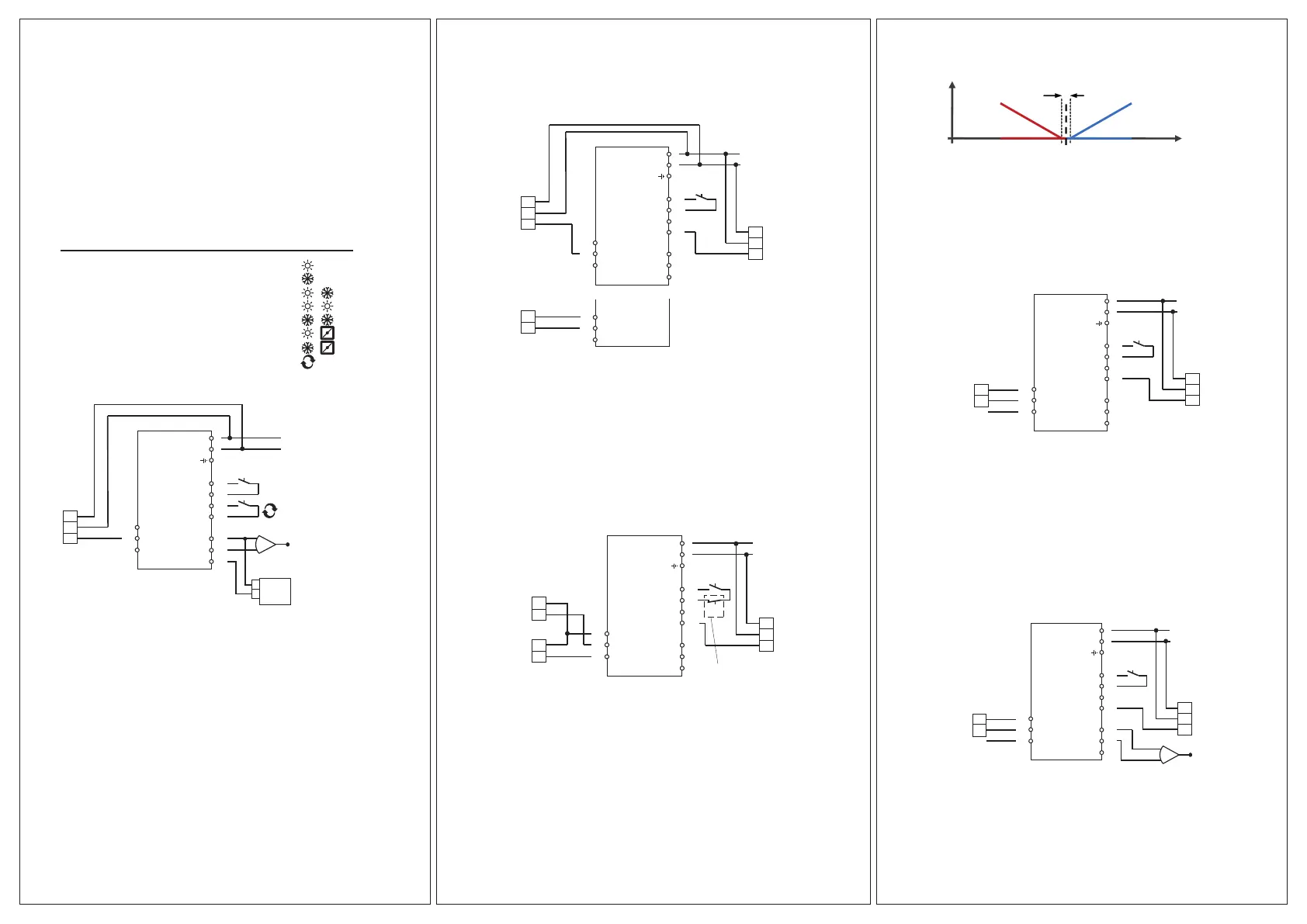
Control modes
CMF can be congured to any one of the following control modes:
1. Temperature control
The temperature at the sensor is kept at the setpoint value by
controlling the output signals on AO1 and AO2. The setpoint can
be set directly from the display or via an external setpoint device.
A single PI control loop is used.
The analogue outputs can be congured to the following combi-
nations:
AO1 AO2 Display symbols
1
2
3
4
5
6
7
8
Heating
Cooling
Heating
Heating
Cooling
Heating
Cooling
Change-over
-
-
Cooling
Heating
Cooling
Damper
Damper
-
\
/
\ /
\ \
/ /
\ /
\ /
24 V AC
Start signal
+
-
G
G0
DI+
DI1
UI+
UI1
A
GND
AI1
SPI
1
2
3
41
42
43
44
50
51
52
20
21
22
A
GND
AO1
-
°C
G0
G
Y
SAP-
PT1000-1
3
4
Figure 1. Wiring example: Heating/cooling with change-over function
and external setpoint device.
Level 1.6 of the menu is used for selecting the temperature operating
range. Here, it is possible to select:
Low (1) -20...+60°C Min. setpoint= -18, max.= +60
Medium (2) 20...100°C Min. setpoint= 22, max.= 100
High (3) 60...140°C Min. setpoint= 62,max.= 140
2. CO
2
control
The CO
2
-value at the sensor is kept at the setpoint value by
controlling the output signal on AO1. A single PI control loop is used.
Min./max. limitation of the output is possible.
24 V AC
Damper
Frequency
converter
CO
2 transmitter
G
G0
DI+
DI1
UI+
UI1
A
GND
AI1
SPI
1
2
3
41
42
43
44
50
51
52
20
21
22
A
GND
AO1
AO2
G0
G
S
G0
G
Y
20
21
22
AGND
AO1
AO2
-
+
0...10V
Start
signal
Figure 2. Wiring example: CO
2
control using damper or frequency
converter.
3. General control
The setpoint at the sensor is returned by controlling the output
signals on AO1 and AO2. AO1 is used for negative control, AO2 for
positive control. A single PI control loop is used.
If you want to max. limit the humidity, connect a DBKH-10H humi-
distat in series with the start signal to terminals 41 and 42.
24 V AC
Start
signal
Humidity
transmitter
Humidifier
Dehumidifier
DBKH-10H Max limiting
humidistat
G
G0
DI+
DI1
UI+
UI1
A
GND
AI1
SPI
1
2
3
41
42
43
44
50
51
52
20
21
22
A
GND
AO1
AO2
-
+
-
+
% RH
G0
G
S
0...10V
Figure 3. Application example: Combined humidication/dehumidica-
tion.
Setpoint
Temp. (°C)
AO2
AO1
Negative control,
reverse-acting
Positive control,
direct-acting
Above graph drawn as during pure P control
4. Pressure control
The pressure at the sensor is kept at the setpoint value by
controlling the output signal on AO1. A single PI control loop is
used. The AO1 inverted signal is recieved from AO2.
24 V AC
Start
signal
Pressure
transmitter
0...10V
Frequency
converter
Pa
G
G0
DI+
DI1
UI+
UI1
A
GND
AI1
SPI
1
2
3
41
42
43
44
50
51
52
20
21
22
A
GND
AO1
AO2
G0
G
Y
-
+
AO1 inverted signal
Figure 4. Wiring example: Pressure control.
5. Pressure control with outdoor compensation
The pressure at the sensor is kept at the setpoint value by
controlling the output signal on AO1. The setpoint is automati-
cally adjusted according to the outdoor temperature. A single PI
control loop is used. When this control mode is used, the
temperature range is adjusted down to the low setting
(-20...+60°C). The AO1 inverted signal is recieved from AO2.
24 V AC
Start
signal
Pressure
transmitter
0...10V
Outdoor temp
sensor
Frequency
converter
Pa
G
G0
DI+
DI1
UI+
UI1
A
GND
AI1
SPI
1
2
3
41
42
43
44
50
51
52
20
21
22
A
GND
AO1
AO2
G0
G
Y
-
+
°C
AO1 inverted signal
Figure 5. Wiring example: Outdoor temperature compensated pressure
control.
 Loading...