INETVU® MOBILE SYSTEM QUICK START – NERA & STM
C-COM Satellite Systems Inc. Page 9
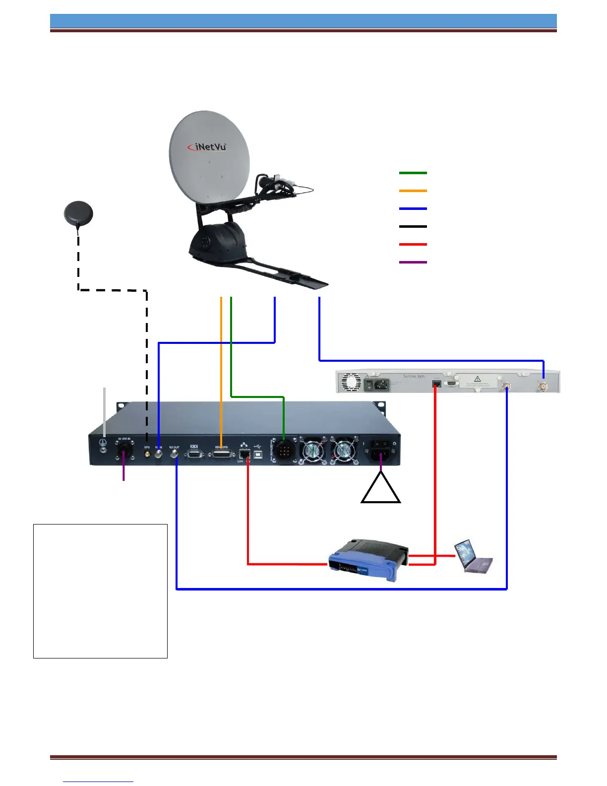
1.7 Network Interface Connection – System Wiring
3.
Network Interface System Wiring Diagram for STM Service
Cable
Cable
SAT IN
SUB: 255.X.Y.Z
GW: A.B.C.D
SUB: 255.X.Y.Z
Network Cable
OUT
Motor Control Cable
Sensor Cable
RG6 Coaxial Cable
USB Cable
Network Cable
Power Cable
Network Cable
SUB: 255.X.Y.Z
GW: A.B.C.D
With a NETWORK Connection
from a PC to the controller, the
software application OR Web
Interface may be used to
configure the controller, as
well as to perform automatic
satellite acquisition, and stow
functions. If the user wishes
not to use a PC, the controller
is fully configurable from the
front screen and NO PC would
be required to be connected
via Network
Antenna
protection
Input
(option)