Do you have a question about the Infineon ERU Interrupt 1 and is the answer not in the manual?
Details the implementation of an ISR triggered by ERU for blinking an LED, including priority and CPU core assignment.
The External Request Unit (ERU) is a versatile event and pattern detection unit primarily designed for generating interrupts based on selectable trigger events at various inputs. It can detect rising and falling edges at an input pin and use these events to generate external interrupt requests. Beyond interrupt generation, the detected events can also be utilized by other modules to trigger or gate module-specific actions.
To generate an interrupt via falling and rising edges on an input pin, several configuration steps are required. First, the external request pin needs to be initialized using IfxScuEru_initReqPin(). Next, the specific edges that should trigger the interrupt are selected using IfxScuEru_enableRisingEdgeDetection() for rising edges and/or IfxScuEru_enableFallingEdgeDetection() for falling edges. After selecting the trigger edges, the generation of trigger events must be enabled with the function IfxScuEru_enableTriggerPulse().
The output channel for the trigger event is then chosen by selecting the Output Gating Unit (OGUz) and the trigger pulse output (TRxz). An event from the Event Trigger Logic (ETL0) triggers the OGU0 (signal TRx0), and the function IfxScuEru_connectTrigger() determines the output channel for this trigger event. Finally, the condition to generate an interrupt is set using IfxScuEru_setInterruptGatingPattern(), and the service request is configured and enabled with IfxSrc_init() and IfxSrc_enable(). These functions are provided by the iLLD headers IfxScuEru.h and IfxSrc.h.
The device supports an Interrupt Service Routine (ISR) for handling these interrupts. Blinking an LED is a common implementation within an ISR triggered by the ERU. The method implementing the ISR needs to be assigned a priority and a CPU core responsible for its execution, which is done using the macro IFX_INTERRUPT(isr, vectabNum, priority). When triggered, the ISR can blink an LED by toggling the state of the connected pin using the function IfxPort_setPinState().
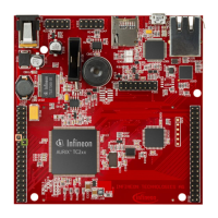
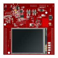
For hardware setup, the code example is developed for the KIT_AURIX_TC297_TFT_BC-Step board. Specifically, pins P02.0 and P02.1 need to be connected to each other. P02.1 is used to generate falling and rising edges by toggling its state from high to low. P02.0 serves as the input to the ERU, which then generates interrupts on these falling and rising edges.
After code compilation and flashing the device, the following steps are performed for testing:
LEDstate variable within the g_ERUconfig structure using a debugger.The AURIX™ Development Studio is available online for development, and its "Import..." function provides access to more code examples. Additional code examples can be found on the GIT repository at https://github.com/Infineon/AURIX_code_examples. For further training, the Infineon webpage https://www.infineon.com/aurix-expert-training is available. Questions and support can be directed to the AURIX™ Forum at https://www.infineonforums.com/forums/13-Aurix-Forum.
The information provided is intended for technically trained staff, and it is the customer's responsibility to evaluate the product's suitability for their intended application and the completeness of the product information. Products may contain dangerous substances due to technical requirements, and information on these types can be obtained from the nearest Infineon Technologies office. Infineon's products are not to be used in applications where a failure could result in personal injury, unless explicitly approved in writing by authorized representatives.
| Brand | Infineon |
|---|---|
| Model | ERU Interrupt 1 |
| Category | Control Unit |
| Language | English |