Do you have a question about the Infineon GTM TIM Capture 1 and is the answer not in the manual?
Specifies connecting P02.0 for TIM input and P02.3 for TOM output.
Details enabling GTM/CMU clocks and initializing TIM configuration structures.
Lists iLLD functions like update(), getPeriodSecond(), and getDutyPercent() for measurement.
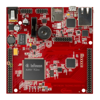
The document describes a training module for the AURIX™ TC2xx Microcontroller, specifically focusing on the GTM_TIM_Capture_1 example, which involves PWM input capturing via the Timer Input Module (TIM).
The core function of this training module is to demonstrate how to capture an external Pulse Width Modulation (PWM) signal using the Timer Input Module (TIM) of the Generic Timer Module (GTM) on an AURIX™ TC2xx microcontroller. Once the PWM signal is captured, the system calculates its frequency and duty cycle in software. These calculated values are then stored in variables for further use or display.
The Generic Timer Module (GTM) is a versatile, modular timer unit designed to accommodate a wide range of timer applications. Within the GTM, the Timer Input Module (TIM) is specifically responsible for filtering and capturing incoming input signals. The Clock Management Unit (CMU) plays a crucial role in generating the necessary clocks for the GTM. Its Configurable Clock Generation Subunit (CFGU) provides eight distinct clock sources for various GTM submodules, including the TIM, Timer Base Unit (TBU), Monitor (MON), and Advanced Timer for Automotive Applications (ATOM).
In addition to the TIM, the GTM also incorporates an in-built Timer Output Module (TOM). The TOM is capable of offering 16 independent channels, which can be used to generate output signals, such as the PWM signal used as an input in this example. The CMU is also responsible for clock generation for the TOM. Its Fixed Clock Generation (FXU) subunit provides five predefined, non-configurable clocks for GTM modules, including the TOM.
While specific technical specifications like voltage ranges or current consumption are not detailed in this document, the following operational parameters and components are highlighted:
The training module outlines a clear process for configuring and using the TIM and TOM for PWM capture and generation:
Configuration of TIM:
IfxGtm_enable().IfxGtm_Cmu_enableClocks().IfxGtm_Tim_In_Config structure with default parameters via IfxGtm_Tim_In_initConfig().IfxGtm_Tim_In_Config, including:
filter.inputPin: Selection of the input port pin (e.g., P02.0).filter.inputPinMode: Selection of the input mode (e.g., IfxPort_InputMode_pulldown).IfxGtm_Tim_In_init().IfxGtm_Tim_In.h.Configuration of TOM (for PWM generation):
IfxGtm_Cmu_enableClocks().IfxGtm_Tom_Pwm_Config structure with default values via IfxGtm_Tom_Pwm_initConfig().IfxGtm_Tom_Pwm_Config, including:
tom: Selection of the TOM module.tomChannel: Selection of the channel driving the output port pin.period: Desired period for the PWM signal.dutyCycle: Desired duty cycle for the PWM signal.pin.outputPin: Selection of the output port pin (e.g., P02.3).synchronousUpdateEnable: Enabling synchronous update of the timer.clock: Selection of the clock for PWM generation.IfxGtm_Tom_Pwm_init().IfxGtm_Tom_Pwm_start().IfxGtm_Tom_Pwm.h.Measuring PWM Frequency and Duty Cycle:
IfxGtm_Tim_In_update().IfxGtm_Tim_In_getPeriodSecond().frequency(Hz) = 1 / period(s).IfxGtm_Tim_In_getDutyPercent().IfxGtm_Tim_In.h.Testing and Debugging:
g_measuredPwmFreqHz and g_measuredDutyCycle to the debugger's Watch Expressions.The document does not explicitly detail maintenance features for the hardware itself. However, it provides resources for ongoing support and development:
https://github.com/Infineon/AURIX_code_examples.https://www.infineon.com/aurix-expert-training.https://www.infineonforums.com/forums/13-Aurix-Forum.erratum@infineon.com) is provided for questions regarding the document.| Brand | Infineon |
|---|---|
| Model | GTM TIM Capture 1 |
| Category | Control Unit |
| Language | English |