S
Sarah BarkerJul 30, 2025
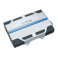
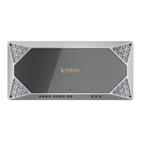
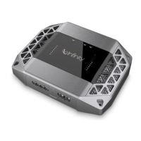
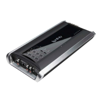
How to fix distorted audio in Infinity 7540a?
- RRachel LeeJul 30, 2025
If you are experiencing distorted audio with your Infinity Amplifier, the input sensitivity might not be set correctly, or there could be a defect in the amplifier or source unit. First, check the INPUT LEVEL setting. Also, inspect the speaker wires for any shorts or grounds.